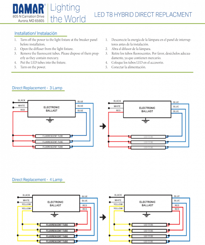
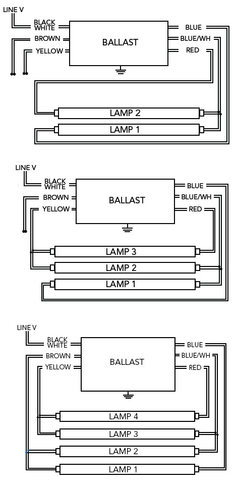
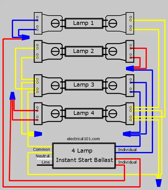
37 4 lamp t5 ballast wiring diagram
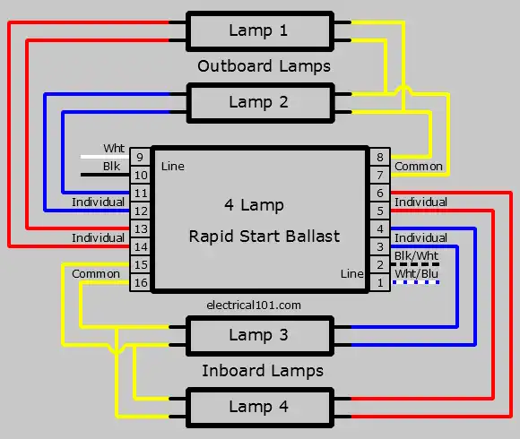
4 lamp t5 ballast wiring diagram – Sunpark Lighting Democraciaejustica 4 Lamp 2 Ballast Wiring Diagram Download. File Type: JPG. Source: galericanna.com. Variety of 4 lamp t5 ballast wiring diagram. Click on the image to enlarge, and then save it to your computer by right clicking on the image. Rapid Start Ballast Wiring (4 Lamps) Rapid Start ballasts use two wires for connections to each end of a fluorescent tube. This series wiring uses a non- shunted lampholder, with each side of the lampholder isolated from the other side. With a two lamp rapid start ballast, if one lamp fails the other lamp connected to that ballast will not light.
17 Jan 2013 — Looking at the ballast wiring diagram, black, white, and grey wires to orange quick disconnect. Line on diagram going to grey has a symbol ...

4 lamp t5 ballast wiring diagram
Variety of 4 lamp t5 ballast wiring diagram. A wiring diagram is a simplified standard photographic representation of an electric circuit. It shows the elements of the circuit as simplified forms, as well as the power as well as signal links in between the gadgets. and DULUX® L T5 lamps with full lumen output and optimal system ... 4-lamp “switching” ballast, designed to ... nating “wrong voltage” wiring errors and.4 pages 2. Select the appropriate wiring diagram to connect the emergency ballast to the AC ballast and lamp. Make sure all connections are in accordance with the National Electrical Code and any local regulations. manufacturer. 3. Install the test switch through the ballast channel cover of a troffer or through the side of a strip fixture. Drill a
4 lamp t5 ballast wiring diagram. Lamps contain mercury, dispose according to local, state, or federal laws. NOTICE. If supply wires are located within 3 inches of ballast, use wire rated for at ...2 pages With some 3 and 4-lamp programmed start ballasts (wired in series-parallel), if a single lamp in one branch fails, the lamp(s) in the parallel branch will continue to operate. Rapid start ballasts can only be wired in series according to the diagram on the ballast. 4 LH 5 LAMPS WORKHORSE LONGHORSE 1. Find your lamp type. 2. On left, find the quantity and wattage of your lamps. 3. Look across the grid to find your ballast. 4. Find the corresponding wiring diagram on pages 11-12. 5. Check ballast dimension key to ensure correct sizing. LAMP CHART BALLAST DIMENSIONS PG. 10 WH WH WH T5 Light Wiring Diagram . T5 light wiring diagram t5 lamp wiring diagram t5 led tube light wiring diagram vw t5 fog light wiring diagram vw t5 interior light wiring diagramT5 Ballasts Wiring Diagram . T5 ballasts wiring diagram4 Tube Ballast Wiring . 4 tube ballast wiring 4 tube t5 ballast wiring ge t12 ballast … Read More
ELECTRONIC FLUORESCENT BALLASTS 173 Lamp Tpe Input Volts Prouct Number Prouct Coe Line Current Amps Input Power Watts Power Factor Ballast Factor THD Min. Start Temp Wire Diag. Case ... T5 Case diagrams and wiring diagrams can be found on pages 175-177. TOC. ELECTRONIC FLUORESCENT BALLASTS 174 Lamp Tpe Input Volts Prouct Number Prouct Coe Line ... Lamps contain mercury, dispose according to local, state, or federal laws. NOTICE. If supply wires are located within 3 inches of ballast, use wire rated for at ...2 pages HID BALLAST KIT WIRING DIAGRAMS. MAGNETIC FLUORESCENT BALLAST WIRING DIAGRAMS. 1 - LOW WATT MH/HPS QV ... 2 - T5 4 LAMP. 7- PULSE START MH. 9 - 5-TAP HPS.1 page Wiring diagrams and installation examples, page 6. PC T5 PRO lp ... T5 high output, T8 and TC-L fluorescent lamps (CFL) ... For luminaires with 3 or 4 lamps.6 pages
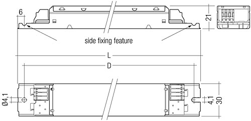
t5 4 lamp ballast wiring diagram wiring diagram load. Architectural wiring diagrams ham it up the approximate locations and interconnections of receptacles, lighting, and steadfast electrical facilities in a building. Interconnecting wire routes may be shown approximately, where particular receptacles or fixtures must be on a common circuit. 4-Lamp Electronic Instant Start. Retrofit Wiring Diagrams. Notes: - This is applicable for 4-lamp T12 rapid start fixture with two 2-Lamp ballasts to ...1 page Description: Wiring Fluorescent Light Ballast Replacement – Wiring Diagram And in 4 Lamp T5 Ballast Wiring Diagram, image size 800 X 522 px, and to view image details please click the image.. Truly, we have been noticed that 4 lamp t5 ballast wiring diagram is being just about the most popular issue at this moment. So that we tried to uncover some terrific 4 lamp t5 ballast wiring diagram ... 2. Select the appropriate wiring diagram to connect the emergency ballast to the AC ballast and lamp. Make sure all connections are in accordance with the National Electrical Code and any local regulations. manufacturer. 3. Install the test switch through the ballast channel cover of a troffer or through the side of a strip fixture. Drill a
and DULUX® L T5 lamps with full lumen output and optimal system ... 4-lamp “switching” ballast, designed to ... nating “wrong voltage” wiring errors and.4 pages
Variety of 4 lamp t5 ballast wiring diagram. A wiring diagram is a simplified standard photographic representation of an electric circuit. It shows the elements of the circuit as simplified forms, as well as the power as well as signal links in between the gadgets.

Buy 4ft 24w T5 High Output Led Tube Light 45 75 F54t5 Equal 5000k Cool White Clear Lens 3500 Lm G5 Mini Base 100 277v Ballast Bypass Dual End Powered Led Shop Light Ul Listed 4 Pack

What Is Direct Wire Ballast Bypass Led Lighting What Is Ballast Operated Plug And Play Led Lighting And How Are They Different Atlantalightbulbs Com

Philips Advance Icn4s5490c2lsg 4 Lamp T5 Ballast 4 54wt5 Ho 120 277v 20c To 90c Electrical Ballasts Amazon Com

Florescent Ballast Repair Wires Don T Match Old Magnetic To New Electronic Color Wire Different Youtube

Buy Fulham Lighting Wh2 120 C Workhorse 2 Versatile Fluorescent Lamp Ballast 120v Online In Indonesia B001p1zknk









0 Response to "37 4 lamp t5 ballast wiring diagram"
Post a Comment