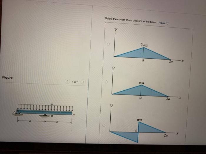
37 select the correct shear diagram for the beam.
Part a draw the shear diagram for the beam. Answer to part a select the correct shear diagram for the beam. Draw the shear and moment diagrams for beam figure 1 posted on march 26 2019 by admin fundamental problem 7 18 add vertical line off segment u roset holp part a draw the shear diagram beams strain stress deflections the beam or flexural ... Transcribed image text: Select the correct shear diagram for the beam. (Figure 1) 2wa Figure ( 1011 2wa -2wa Select the correct moment diagram for the beam ...
Neglect the weight of the beam. 8N B. Sum of vertical force is equal to zero i. the change in M = area under the V This is an example problem that will show you how to graphically draw a shear and moment diagram for a beam. 5 kft 5 Ft + 5 Ft M D 1. The bending moment diagram should be continuous - no steps. There are 3 sections. Draw shear force and bending moment diagrams for the beam. A ...

Select the correct shear diagram for the beam.
Transcribed image text: Part A Select the correct shear diagram for the beam (Figure 1) V WL * 5L 8 L WL 4 V WL 뿡 X ЗwL. 21.09.2021 · Before we expound, let’s go back to clause 6.2.2 (6) which specifies how shear enhancement should be applied: If we . Continue reading. August 28, 2021 Insights/Sensibility Checks. Gains From Being “Left Behind” Picture these: You saw your former teammates checking the drift of an elegant looking ETABS model of a new building. Continue reading. August 25, 2021 ETABS / … 25.05.2020 · Shear stress is caused when the forces applied to an object are parallel to the object's cross-section. This stress can cause the object to deform and, in some cases, pull apart. As the object ...
Select the correct shear diagram for the beam.. Select the correct shear diagram for the beam figure 1. Solution 43 1 simple beam. This preview has intentionally blurred sections. Shear and bending moment. Shear and bending moment diagrams for beam ab and determine the maximum. As shown in the figure below a uniform beam is supported by a cable at one. Calculate the reactions at the supports of a beam, frame and truss. This beam calculator is designed to help you calculate and plot the Bending Moment Diagram (BMD), Shear Force Diagram (SFD), Axial Force Diagram. Select the correct shear diagram for the beam figure 1. This is the end of the preview. Draw the moment diagram for 10 points bonus for the beam shown in the figure below draw the shear diagram. Show all your work bonus points. In the figure below block 1 of mass m 1 slides from rest along a frictionl. The intensity of which varies from zero at ... Choose the correct moment diagram for the beam. Follow the sign convention. This problem has been solved! See the answer ...
Fig. 2.7: Diagram of T and I-beam Most beams in reinforced concrete buildings have rectangular cross sections, but a more efficient cross section for a beam is an I or H section which is typically ... Shear modulus of elasticity of steel: This guide briefly showcases the latest Steel Product and Design/Fabrication Software used by civil and structural engineers throughout the industry. Think of a steel beam sitting, on bolted, with 8 inches bearing on a 12” concrete wall. 3. 1 s y w A f Footing Design fluid level L L grade 16′ 6′ This section contains information on how to define and ... 21.02.2015 · Structural Beam. Structural Beams come in various shapes and sizes so it is important to use the correct terminology when measuring. Beam Terms. Beam Depth: The distance from the top and bottom surface of the steel (see “A” in diagram). Flange Width: The top and bottom flat horizontal sections width (“B”). For The Beam And Loading Shown A Select Correct Shear Bending Moment Diagrams B Determine Equations Of Curves Study. Problem 9 1 Two Beam Segments Ac And Cd Are Connected Together At C By A Frictionless Pin Segment Is Cantilevered From R. 329 6 1 Draw The Shear And Moment Diagrams For Shaft Bearings At A B Exert Only Vertical Reactions On.
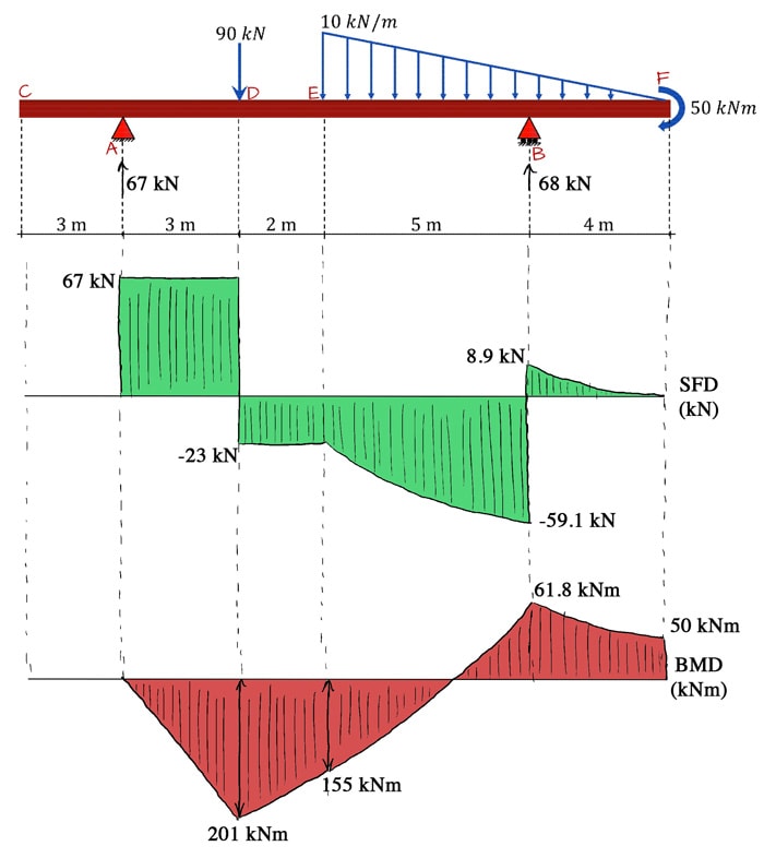
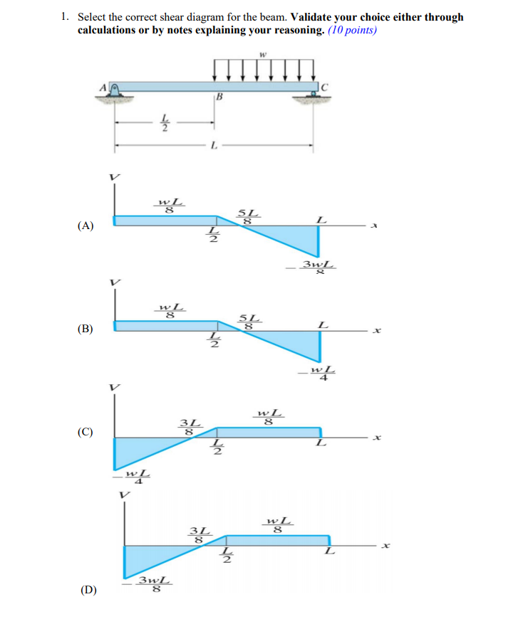
Answer to part a select the correct shear diagram for the beam. 1 simply supported beam with 2 point loads first of all we need to calculate the reactions or shear force at the supports. Part b identify the m. Calculate the shear force at both supports and show the shear force diagram. If you inadvertently place two vertical lines at the same ... Solved w Jс В Select the correct shear diagram for the | Chegg.com. Engineering. Civil Engineering. Civil Engineering questions and answers. w Jс В Select the correct shear diagram for the beam. (Figure 1) w L 3L 8 L wL 4 w L 5L L х 2 wL V w L 5L L х 2 ЗwL V wL 3L ЗwL 8 Select the correct moment diagram for the beam w L2 9WL2 128 16 L ... Question: 1. Select the correct shear diagram for the beam. Validate your choice either through calculations or by notes explaining your reasoning. (10 points) ... In this particular example, this beam loading-support condition is not part of the table. Therefore, we have no alternative but to use shear and moment diagrams to determine the maximum bending moment in the beam. Steps to draw shear and moment diagrams: 1. Draw a free body diagram of the beam. 2. Determine all the reactions and moments by ...
Solidworks Simulation Beam Diagrams Computer Aided Technology
01.11.2021 · Thanks for getting back. i have sent a download link to your private messages as the model file is large. in relation to your comments i don't think the issue is the columns with the shear walls, which as you say would attract axial loads due to them being located within the shear walls, as this is what you would generally expect even thou in the model i have completely released the vertical ...

April 2021 Product Update What S New Fusion 360 Blog
True. T/F: A cantilever beam AB was supported at A, and had a negative area of the M/EI diagram due to the negative bending moment M. Based on the second moment-area theorem, the tangent deviation from A to B is negative. Does it mean the point B is below the tangent at A which is aligned with the x direction. True.
Accessengineeringlibrary Com
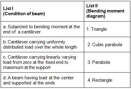
Q 6 For the shear force diagram shown in given figure The loaded beam will be Q 7 Match List-I (Type and position of force on cantilever) with List-II (Shape of moment diagram for cantilever) and select the correct answer using the codes given below the lists:
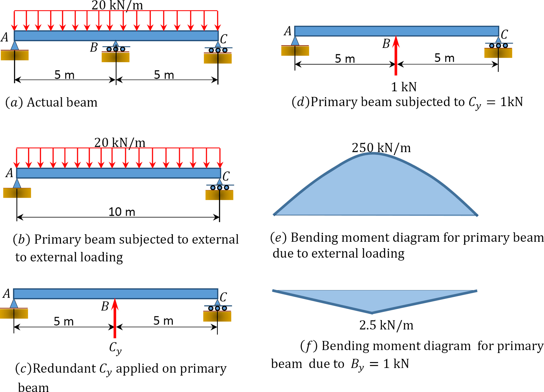
1 10 Force Method Of Analysis Of Indeterminate Structures Engineering Libretexts
Question: Part A Select the correct shear diagram for the beam (Figure 1) V 2wa o X 2a Figure < 1 of 1 > - Zwa 2wa . Za V wa a 2a -wa V wa x а 2a Part B. Select ...
Improving Axial Localization Of Weak Phase Particles In Digital In Line Holography
Question: Part A Select The Correct Shear Diagram For The Beam. (Figure 1) Wa 2a -wa 2wa 2wa X. 2a -2wa Wa -Part B Select The Correct Moment Diagram For The Beam. 2a 2a 2a 24. This problem has been solved! See the answer. Show transcribed image text. Expert Answer 100% (25 ratings)

Shear And Moment Diagram Wikipedia
Below is a screen shot of the line diagram showing the centre line for beam and column layout. Fig 1.Beam and Column Layout using Layers In the above picture the red lines signify the beam centre line while the green rectangular boxes signify the Columns.The beams have a cross section of .300x.400 m. The columns have a cross section of .400x.400 m. Slabs have a uniform thickness of 230mm while ...
Test Bending Moment Shear Force Diagram 2 30 Questions Mcq Test
Select the correct shear diagram for the beam figure 1. Answer to part a identify the shear diagram for the beamfigure 1 identify the shear diagram for the beam. Calculate the shear force at both supports and show the shear force diagram. A beam is shown in the figure below.

For The Beam And Loading Shown A Select The Correct Shear And Bending Moment Diagrams B Determine The Equations Of The Shear And Bending Moment Curves Study Com
Transcribed image text: Select the correct shear diagram for the beam. (Figure 1) 2wa Figure < 1 of wa 2wa -2wa Submit Request Answer Figure 1 of 1 > Part B ...
Shear Force And Bending Moment Diagram
Transcribed image text: Select the correct shear diagram for the beam. 2wa x 2a b) wa a 2a wa MacBook Air a) 2wa X a 2a b) wa a 2a x V wa c) a x 2a - wa V ...
Shear Force And Bending Moment Diagram
25.05.2020 · Shear stress is caused when the forces applied to an object are parallel to the object's cross-section. This stress can cause the object to deform and, in some cases, pull apart. As the object ...
Solved Select The Correct Shear Diagram For The Beam Chegg Com
21.09.2021 · Before we expound, let’s go back to clause 6.2.2 (6) which specifies how shear enhancement should be applied: If we . Continue reading. August 28, 2021 Insights/Sensibility Checks. Gains From Being “Left Behind” Picture these: You saw your former teammates checking the drift of an elegant looking ETABS model of a new building. Continue reading. August 25, 2021 ETABS / …
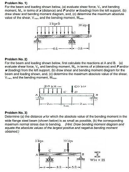
Solved For The Beam And Loading Shown Below A Evaluate Shear Force 1 Answer Transtutors
Transcribed image text: Part A Select the correct shear diagram for the beam (Figure 1) V WL * 5L 8 L WL 4 V WL 뿡 X ЗwL.
Solved For Beams And 2 Below Select The Correct Shear V And Moment M Diagram From The Given Choices And Using Properyertical Dligumnent Draw Lyqlumust Draw The And M Diagu Rams In The Spaces
Dnv Com
Answered The Flexural Strength Of A Bartleby

Achromatic Terahertz Airy Beam Generation With Dielectric Metasurfaces
1 4 Internal Forces In Beams And Frames Engineering Libretexts

A 1 M Long Beam Has A Load Of 5 Kn Applied At Its Center And A Homeworklib

Select The Correct Shear Diagram For The Beam Figure 1 Atkinsjewelry

What S The Difference Between Beam Diagrams Machine Design

Bending Moment And Shear Force Diagram Of A Cantilever Beam

Gate Ce 2009 Shear Force And Bending Moment Question 11 Strength Of Materials Or Solid Mechanics Gate Ce Examside Com
Draw The Shear Diagram For The Beam Home Work Help Learn Cbse Forum
Shear And Moment Diagram Wikipedia
Canadacollege Edu
Select The Correct Shear Diagram For The Beam Figure 1 Study Com

Keywords Keywords Glossary Of Tem Terms Jeol

Study Of Non Uniform Axial Magnetic Field Induced Deformation Of A Soft Cylindrical Magneto Active Actuator Soft Matter Rsc Publishing
The Ultimate Guide To Shear And Moment Diagrams Degreetutors Com
Solved 1 Select The Correct Shear Diagram For The Beam Chegg Com

8 Shear Force And Bending Moment Ppt Video Online Download
Test Sfd Bmd Level 2 20 Questions Mcq Test

Solved W Js V Select The Correct Shear Diagram For The Chegg Com
Shear Force Bending Moment Diagrams Questions And Answers Sanfoundry
Materials Free Full Text Identification Of Fracture Mechanic Properties Of Concrete And Analysis Of Shear Capacity Of Reinforced Concrete Beams Without Transverse Reinforcement Html

Early Breast Cancer Esmo Clinical Practice Guidelines For Diagnosis Treatment And Follow Up Annals Of Oncology

Bending Moments And Shear Force Physics Quiz Quizizz
0 Response to "37 select the correct shear diagram for the beam."
Post a Comment