38 consider the circuit diagram depicted in the figure
Consider the circuit diagram depicted in the figure. Consider the circuit diagram depicted in the figure. It is known that two 25ω 24v and ε2 36v. What equation do you get when you apply the loop rule to the loop abcdefgha in terms of the variables in the figure. Find the values of the voltage vc and the current ib. P 5.2-2 Consider the circuit of Figure P 5.2-2. Find i a by simplifying the circuit (using source transformations) to a single-loop circuit so that you need to write only one KVL equation to find i a. Figure P 5.2-2 . Solution: Finally, apply KVL: 16 10 3 4 0 2.19 A aa 3 a
We will use the circuit of Figure 1 for a step by step demonstration of the node method. Figure 2 shows the implementation of steps 1 and 2. We have labeled all elements and identified all relevant nodes in the circuit. R1 R2 R3 R4 Vs + _ n1 n2 n3 n4 Figure 2. Circuit with labeled nodes. The third step is to select one of the identified nodes ...
Consider the circuit diagram depicted in the figure
Consider the circuit diagram depicted in the fgure. It is known that two battery internal resistors r1and r2 are both 0.2Ω· = 12V and & = 24V. R2 16Ω 2. and Rs 262, but Ri is unknown. Caution: Current directions. Oct 16, 2017 · Consider the circuit diagram depicted in the figure. 0 ω r 3 16. For the action depicted in the figure figure 2 indicate the direction of the induced current in the loop clockwise counterclockwise or zero when seen from the right of the loop. Now consider a diagram describing a parallel ac circuit containing a resistor a capacitor and an inductor. For the original problem setup and the derivation of the above transfer function, please consult the Inverted Pendulum: System Modeling page.. System structure. The structure of the controller for this problem is a little different than the standard control problems you may be used to.
Consider the circuit diagram depicted in the figure. 6.2.2011 · Consider the instant, t = 0, when the switch in Figure 2.13 is closed. In order for any current to flow into the line, the source must see a finite impedance, which we now know to be the characteristic impedance of the line, Z o. The equivalent circuit of this model is shown on Figure 9. R2 + + _ Vp Vn Vi Vo Ip In V in 1 I2 I1 R1 AVi Figure 9. Inverting amplifier circuit model Since our circuit is linear, the voltage at node 1 can be found by considering the principle of superposition. Vn is the sum of voltages Vn o and Vnin as shown on the circuits of Figure 10. The impedance diagram is used for load flow studies. Approximation: (i) The neutral reactances are neglected. (ii) The shunt branches in equivalent circuit of transformers are neglected. Reactance diagram & approximations made in reactance diagram The reactance diagram is the simplified equivalent circuit of power system in which the various Consider this diagram. Let us assume that it describes a series circuit containing a resistor, a capacitor, and an inductor. The current in the circuit has amplitude , as indicated in the figure. Which of the following choices gives the correct respective labels of the voltages across the resistor, the capacitor, and the inductor?
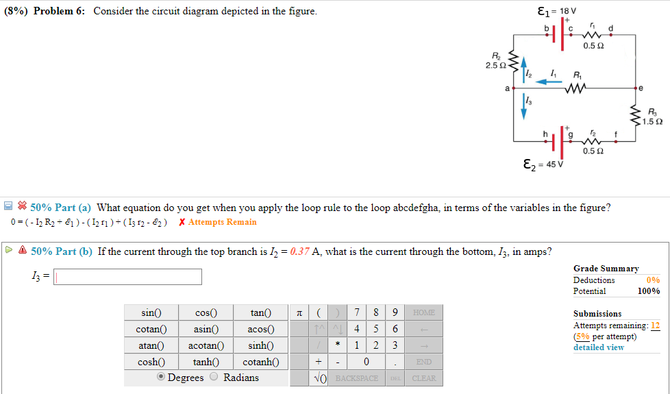
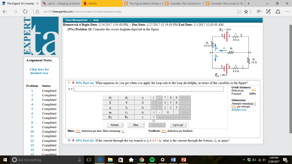
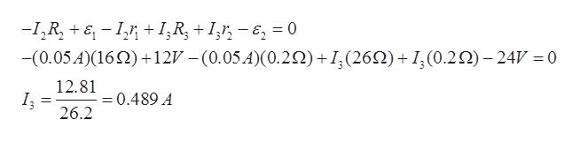
Consider the circuit diagram depicted in the figure. It is known that two battery internal resistors r1and r2 are both 02ω 12v and 24v. Figure 3 the circuit considered in example 2. And rs 262 but ri is unknown. This time the voltage across each of these elements of the circuit is the same. Figure 7.3 shows the state transition diagram for the SITAR system with three redundant COTS servers. Initially, the system is in good state G with no vulnerabilities. Assume that an initial phase of an attack will move the system to the vulnerable state V from state G.During the interval the system is in state V; attackers try various ways to exploit these vulnerabilities in order to cause a ... 2. 27.3.2 (7, ex) Consider the circuit diagram depicted in the figure. (a) What equation do you get when you apply the loop rule to the loop abcdefgha, in terms of the variables in the figure? (b) If the current through the top branch is I2 = 0.085 A, what is the current through the bottom, I3, in amps? (c) Find the current through R 1 and the resistance of R 1. The Thevenin equivalent circuit is obtained after transforming the current source into a´ voltage source V(s) = Z(s)I(s) = RCv c(0) 1+sRC. This sequence of transformations is shown in Figure 3. Question 2 — Laplace domain circuit analysis Figure 4: RC circuit for Laplace analysis. Part (i) [3 marks] Consider the circuit depicted in Figure 4 ...
Transcribed image text: Consider the circuit diagram depicted in the figure. What equation do you get when you apply the loop rule to the loop abcdefgha, in terms of the variables in the figure? If the current through the top branch is I_2 = 0.47 A, what is the current through the bottom. Figure 1. Basic schematic of the electrical properties of a plasma membrane. A: A circuit diagram showing the membrane capacitance and membrane resistance in parallel to each other. B: Traces showing a command voltage step (top) and the resulting current response (bottom) for a simple plasma membrane being voltage clamped. Figure 12.2.2 (a) Time dependence of IR (t) and VR (t) across the resistor. (b) Phasor diagram for the resistive circuit. The behavior of IR (t)and can also be represented with a phasor diagram, as shown in Figure 12.2.2(b). A phasor is a rotating vector having the following properties: VR (t) (i) length: the length corresponds to the amplitude. Sample Circuit We consider the ... Consider the circuit shown in Figure P28.9. Find (a) the current in the 20.0-Ω resistor and (b) the ... Draw the circuit diagram and assign labels and symbols to all known and unknown quantities. Assign directions to the currents.
Analyzing Circuits Via Source Transformation Technical Articles
Nov 16, 2021 · Consider the circuit diagram depicted in the figure. Consider the circuit diagram depicted in the figure. It is known that two 25ω 24v and ε2 36v. What equation do you get when you apply the loop rule to the loop abcdefgha in terms of the variables in the figure. F in d the values of the voltage vc and the current ib.

10 Problem 1 Consider The Circuit Diagram Depicted In The Figure Docx 10 Problem 1 Consider The Circuit Diagram Depicted In The Figure 1 592 Course Hero
For the circuit shown in the figure, calculate (a) the current in the 2.00-Ω resistor and (b) the potential difference between points a and b, ΔV = Vb - Va.
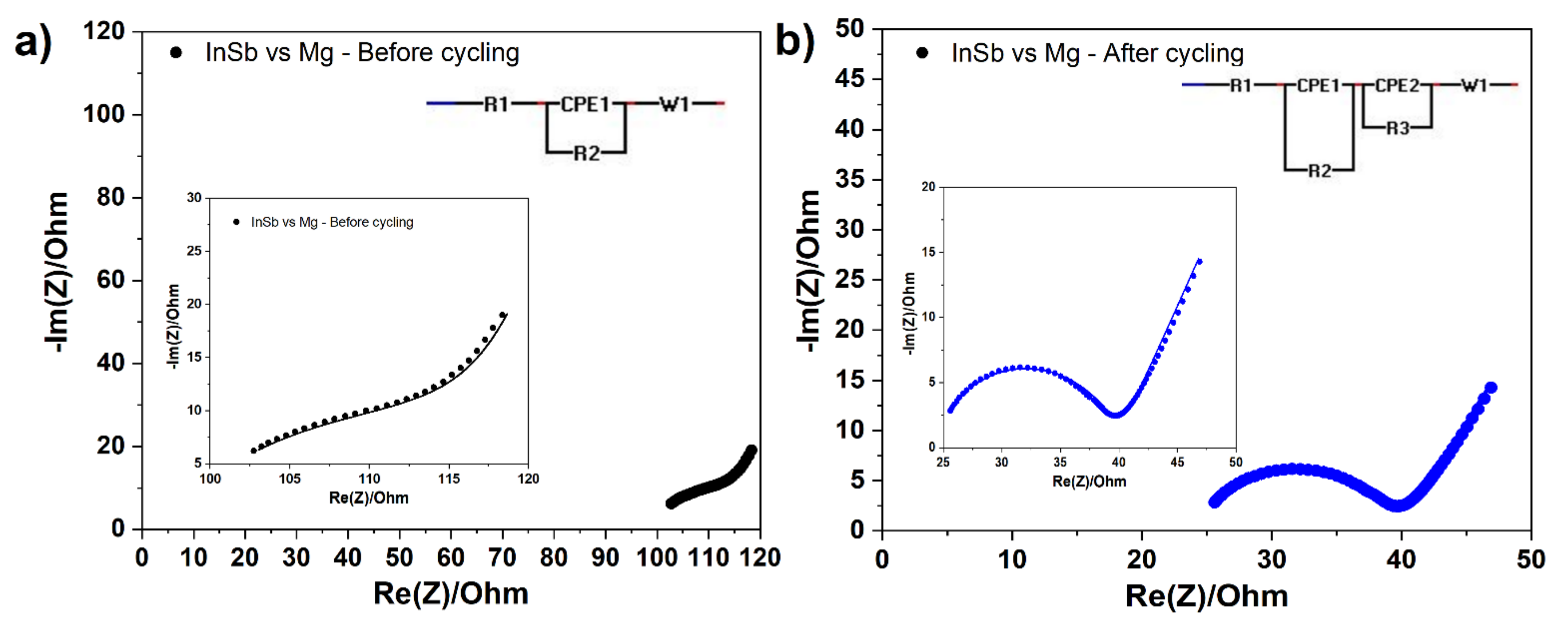
Molecules Free Full Text Influence Of Electrolyte On The Electrode Electrolyte Interface Formation On Insb Electrode In Mg Ion Batteries Html
Figure 6.13. State-assigned table for the sequential circuit in Figure 6.12. Present Next state state Outputs A 00 00 0 1 0 0 0 0 0 0 0 B 01 10 1 0 0 0 1 0 0 1 0 C 10 11 1 1 1 0 0 1 0 0 0 D 11 00 0 0 0 1 0 0 1 0 1
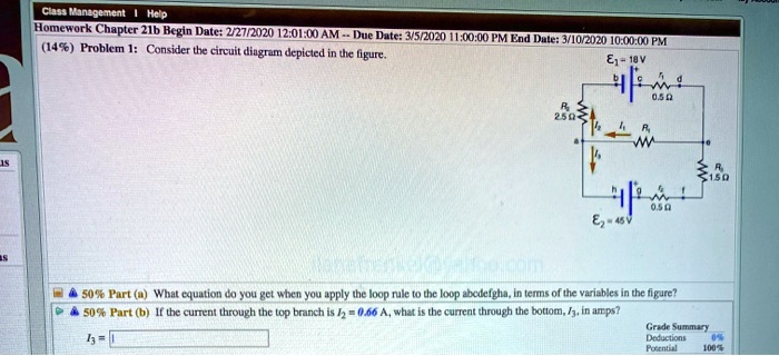
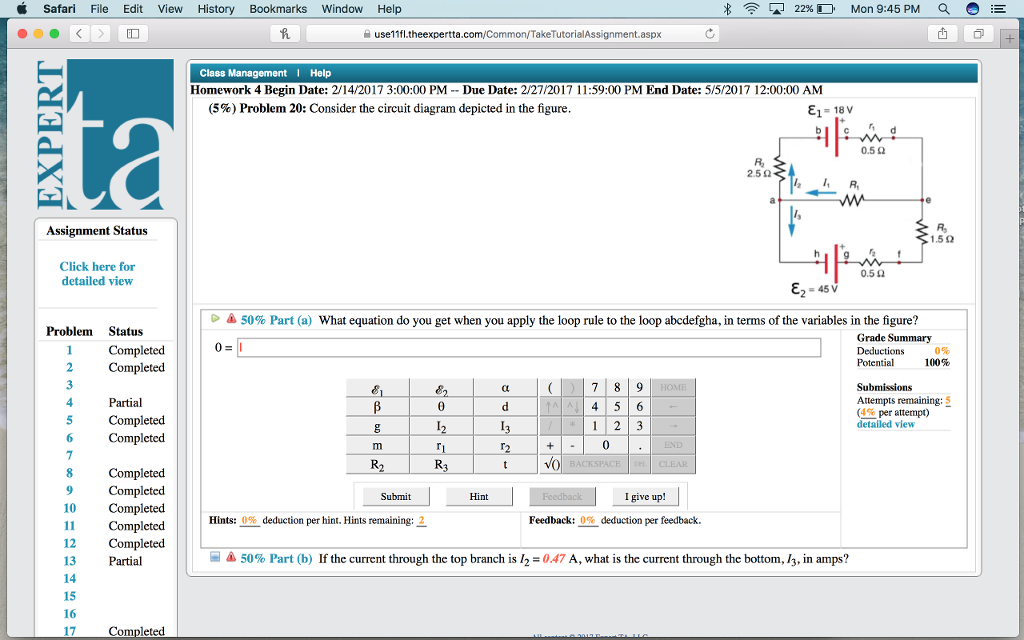
Solved Ciss Wanzoltlent Help Homework Chapter 21b Bcgin Dutc 27 2020 12 01l 00 Am Dute 52030 149 Problem I Consider The Cinuit Diugram Dcpicled Dic Ligurc Meein E7 4sv 50 Fart W What Cquation
Yes. Our services are very confidential. All our customer data is encrypted. We consider our client’s security and privacy very serious. We do not disclose client’s information to third parties. Our records are carefully stored and protected thus cannot be accessed by unauthorized persons. Our payment system is also very secure.

Tmizpdxbfm0oum
16.11.2021 · 4 Recommended Documentation 4.1 Manuals & Schematics. Schematics for each game are essential in tracing down connections to lamps, switches, and solenoids. The owner's game manual is a handy resource to have for general game operation, game settings & diagnostics, switch & lamp matrices, fuse lists, circuit boards and parts, playfield assemblies, some basic schematics, and wiring …

10 Problem 1 Consider The Circuit Diagram Depicted In The Figure Docx 10 Problem 1 Consider The Circuit Diagram Depicted In The Figure 1 592 Course Hero
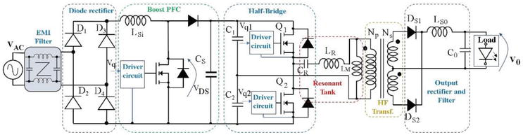
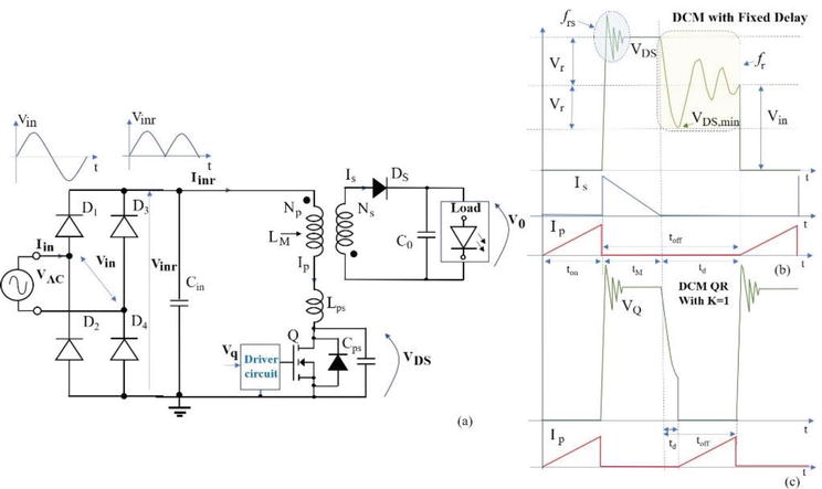
13.7.2019 · Figure 2. Block Diagram of Switching Power Supply Circuit . Ⅳ Principle of Input Circuit and Common Circuit 4.1 Principle of AC Input Rectification and Filtering Circuit. Figure 3. Schematic of Input Filter, Rectifier Circuit. ① Lightning Protection Circuit: When there is a lightning strike, high voltage is generated through the power grid.
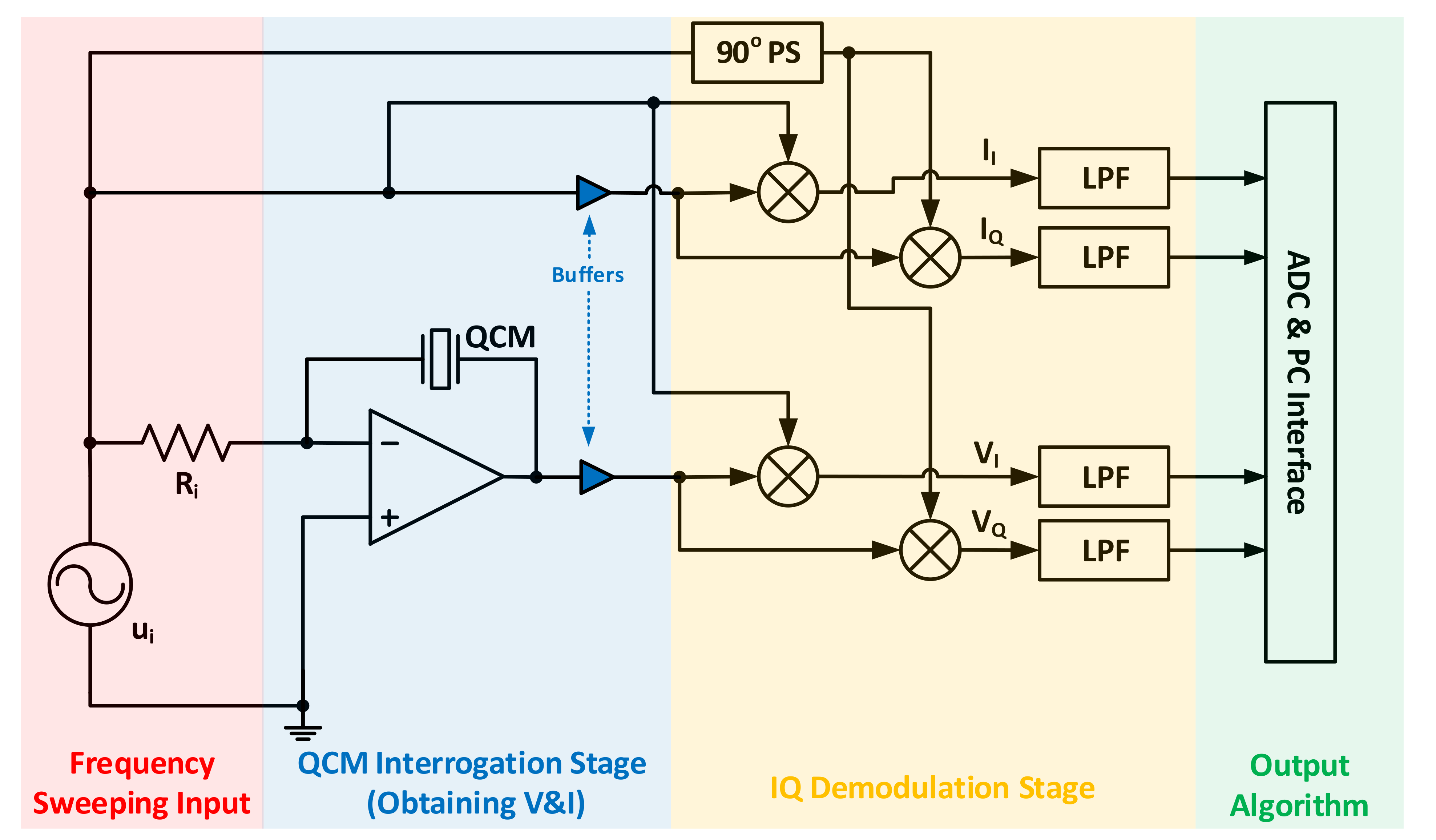
Sensors Free Full Text Quartz Crystal Microbalance Electronic Interfacing Systems A Review Html
Robert L Boylestad - Introductory Circuit Analysis, Tenth Edition. 1220 Pages. Robert L Boylestad - Introductory Circuit Analysis, Tenth Edition. T. Person. Download Download PDF. Full PDF Package Download Full PDF Package. This Paper. A short summary of this …

Exergy Study Of Amine Regeneration Unit Using Diethanolamine In A Refinery Plant A Real Start Up Plant Sciencedirect
91% (345 ratings) Problem Details. Consider the circuit diagram depicted in the figure. Part (a) What equation do you get when you apply the loop rule to the loop abcdefgha? Part (b) If the current through the top branch is I2 = 0.49 A, what is the current through the bottom I3, in amps? Frequently Asked Questions.

Basic Pneumatic Circuits Tech Briefs
Question. Consider the circuit diagram depicted in the figure. What equation do you get when you apply the loop rule to the loop abcdefgha, in terms of the variables in the figure? 0 = If the current through the top branch is I_2 = 0.69 A, what is the current through the bottom, I_3, in amps?

Refer To The Circuit Diagram Depicted In Figure 1 Below 10245v 20 20v 3 4021 10 22 Homeworklib
Transcribed image text: (10%) Problem 5: Consider the circuit diagram depicted in the figure 0.5 Ω R2 2.5 Ω /2 R 1.5Ω 0.5 Ω 50% Part (a) what equation do you get when you apply the loop rule to the loop abcdergha, in terms of the variables in the figure? Grade= 100% Correct Answer Student Final Submission Feedback Correct! 012 R2+ 112 T3 R3 +32-62 0- 1-(Ti +R2) I2+(R3r2)13 2 Grade Summary ...

Refer To The Circuit Diagram Depicted In Figure 1 Below 10245v 20 20v 3 4021 10 22 Homeworklib
Consider the circuit diagram depicted in the figure. a. What equation do you get when you apply the loop rule to the abcdefgha, in terms of the variables in the figure?

L R C Circuit An Overview Sciencedirect Topics
Physics. Physics questions and answers. Consider the circuit diagram depicted in the figure. What equation do you get when you apply the loop rule to the loop abcdefgha? If the current through the top branch is I_2 = 0.49 A. what is the current through the bottom, I_3, in amps? Question: Consider the circuit diagram depicted in the figure.
Passive And Active Topologies Investigation For Led Driver Circuits Intechopen
Consider a series RC circuit as in the figure below for which R = 1.00 MΩ, C = 5.00 µF, and ε = 30.0 V. Find (a) the time constant of the circuit and (b) the...
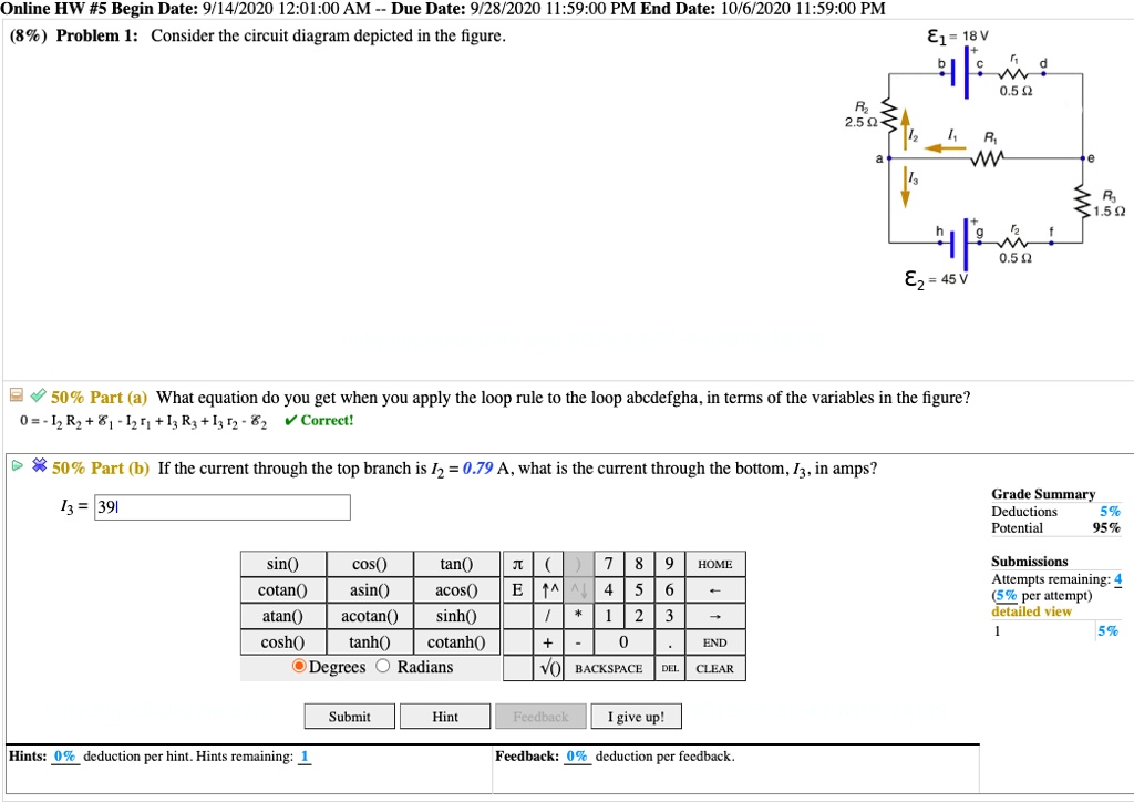
Solved Online Hw 5 Begin Date 9 14 2020 12 01 00 Am Due Date 9 28 2020 59 00 Pm End Date 10 6 2020 1 59 00 Pm 8 Problem 1 Consider The Circuit Diagram Depicted In The Figure 81
Note that all variables may not be required. α, β, θ, a, d, g, h, I 1, I 2, j, k, m, P, S, t Problem 2: Consider the circuit diagram depicted in the figure. Part (a) What equation do you get when you apply the loop rule to the loop abcdefgha, in terms of the variables in the figure?
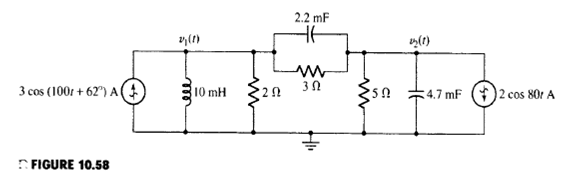
Solved For The Circuit Depicted In Fig 10 58 A Redraw With Ap Chegg Com
EECS 31/CSE 31/ICS 151 Homework 5 Questions with Solutions. View Questions Only View Questions with Strategies. Problem 1 Question (SR latch) Draw the output and timing diagram of a (a) NOR and (b) NAND implementation of an SR latch for the input signals depicted in Figure P6.2.

Consider The Circuit Diagram Depicted In T Clutch Prep
Question Consider the circuit diagram consisting of capacitors and a battery pictured on the board. Find the equivalent capacitance, the charge on each capacitor and the... Question Consider the circuit diagram depicted in the figure. What equation do you get when you apply the loop rule to the loop abcdefgha, in terms...

Do 254 Intro Compliance Free Tools Papers Resources Afuzion
For the action depicted in the figure, (Figure 2) indicate the direction of the induced current in the loop (clockwise, counterclockwise or zero, when seen from the right of the loop). The face of the south pole will become the north pole, so there will be a force of attraction between them, which makes the motion of the coil opposed.
Solved Consider The Circuit Diagram Depicted In The Figure Chegg Com
Consider the circuit diagram depicted in the figure. Now apply the loop rule to loop 1 the larger loop spanning the entire circuit. Assume that v 128 v r1 r2 r3 r4 r5 200 ω. B if the current through the top branch is i 2 0605 a. Consider a series rc circuit as in the figure below for which r 100 mω c 500 µf and ε 300 v.

Schematic Of Li Ion Battery Mechanism 1 With Copyright Permission Download Scientific Diagram
(10%) Problem 1: Consider the circuit diagram depicted in the figure. <1.592 0.50 45 V A 50% Part (a) What equation do you get when you apply the loop rule to the loop abcdefgha, in terms of the variables in the figure? > A 50% Part (b) If the current through the top branch is 12 = 0.83 A, what is the current
F0jpinuvs Ynkm
22.7.2019 · 2. Zener diode symbol figure: This figure needs changing to the symbol that is in the Crowbar circuit ZD1. [See IEEE 315A, Clause 8.3.1 “Breakdown” symbol to be used as the cathode symbol, which is from IEC 60617.] 3. Schottky diode symbol figure: The additional line from the anode to the cathode through the triangle needs to be added.

Modeling And Design Of Single Phase Pv Inverter With Mppt Algorithm Applied To The Boost Converter Using Back Stepping Control In Standalone Mode
The circuit diagram of the two input CMOS NAND gate is given in the figure below. The principle of operation of the circuit is exact dual of the CMOS two input NOR operation. The n – net consisting of two series connected nMOS transistor creates a conducting path between the output node and the ground, if both input voltages are logic high.

Resources Powersim Inc
Consider the circuit shown in Figure (a). i L(0-) = 0, and v R(0-) = 0. But, -v R(0-) + v C(0-) + 10 = 0, or v C(0-) = -10V. (a) At t = 0+, since the inductor current and capacitor voltage cannot change abruptly, the ...

Basic Pneumatic Circuits Tech Briefs
For the original problem setup and the derivation of the above transfer function, please consult the Inverted Pendulum: System Modeling page.. System structure. The structure of the controller for this problem is a little different than the standard control problems you may be used to.
Solved 8 Problem 6 Consider The Circuit Diagram Depicted Chegg Com
Oct 16, 2017 · Consider the circuit diagram depicted in the figure. 0 ω r 3 16. For the action depicted in the figure figure 2 indicate the direction of the induced current in the loop clockwise counterclockwise or zero when seen from the right of the loop. Now consider a diagram describing a parallel ac circuit containing a resistor a capacitor and an inductor.

Accelerating With Flybrainlab The Discovery Of The Functional Logic Of The Drosophila Brain In The Connectomic And Synaptomic Era Elife
Consider the circuit diagram depicted in the fgure. It is known that two battery internal resistors r1and r2 are both 0.2Ω· = 12V and & = 24V. R2 16Ω 2. and Rs 262, but Ri is unknown. Caution: Current directions.
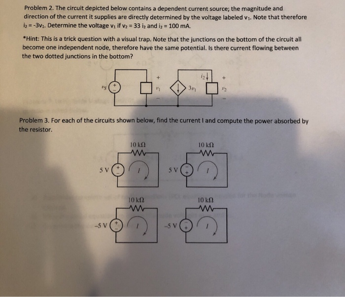
Solved Problem 2 The Circuit Depicted Below Contains A Chegg Com

Refer To The Circuit Diagram Depicted In Figure 1 Below 10245v 20 20v 3 4021 10 22 Homeworklib

Basic Pneumatic Circuits Tech Briefs
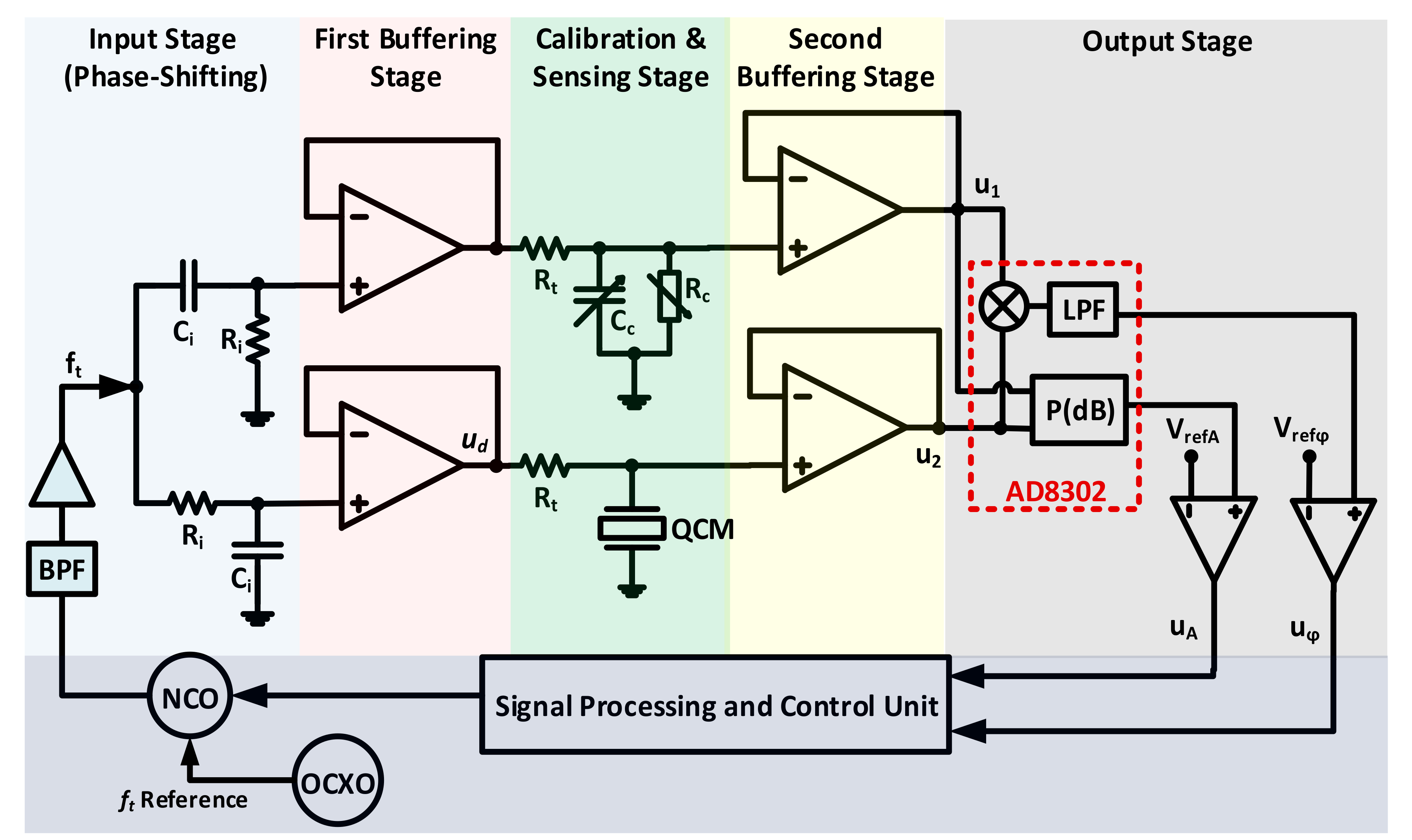
Sensors Free Full Text Quartz Crystal Microbalance Electronic Interfacing Systems A Review Html
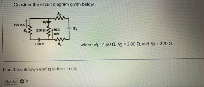
Solved Consider The Circuit Diagram Given Below 195 Ma 2 00 Chegg Com
Passive And Active Topologies Investigation For Led Driver Circuits Intechopen

Book 2 Chapter 17 Regeneration Circuits Hydraulics Pneumatics
Solved Consider The Circuit Diagram Depicted In The Figure Chegg Com
Answered Consider The Circuit Diagram Depicted Bartleby
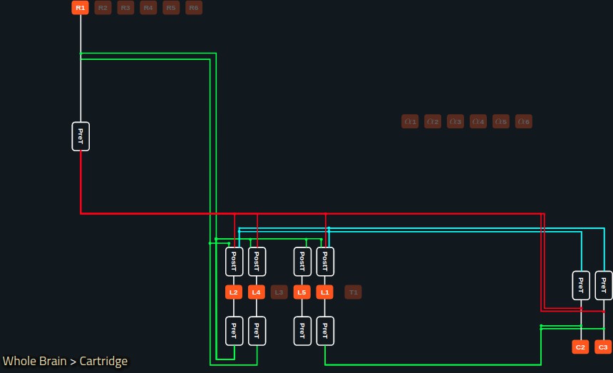
Accelerating With Flybrainlab The Discovery Of The Functional Logic Of The Drosophila Brain In The Connectomic And Synaptomic Era Elife
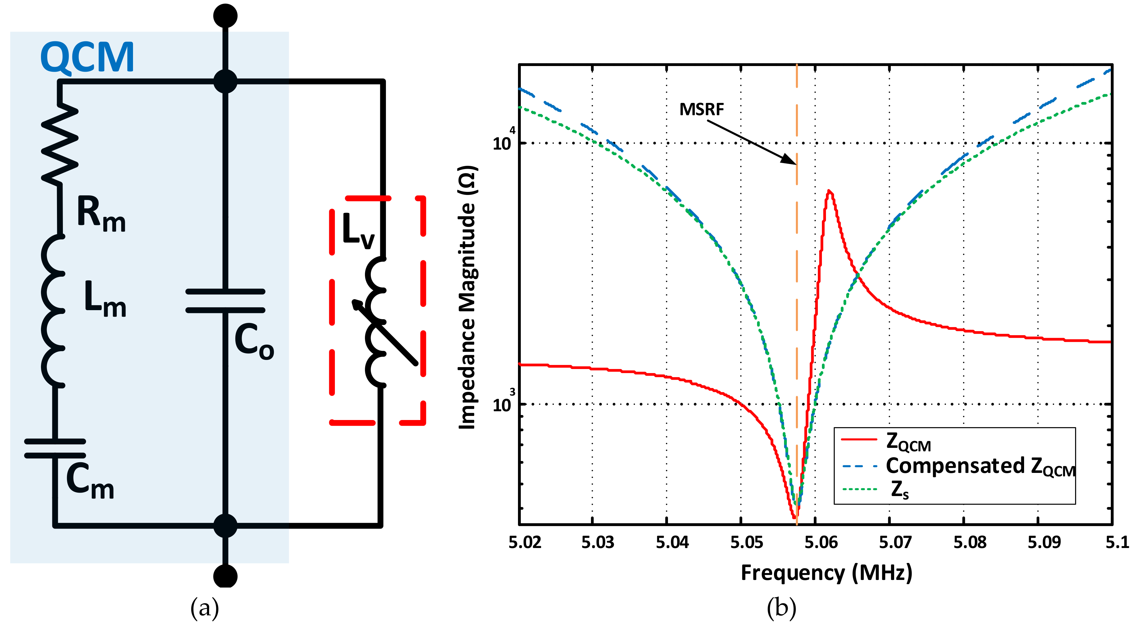
Sensors Free Full Text Quartz Crystal Microbalance Electronic Interfacing Systems A Review Html
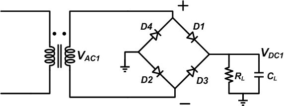
How To Troubleshoot A Diode Bridge Rectifier Technical Articles

44 Types Of Graphs Charts How To Choose The Best One
0 Response to "38 consider the circuit diagram depicted in the figure"
Post a Comment