38 speed tech lights wiring diagram
Primary Speaker. Brown. Primary Speaker. Grey. Radio Rebroadcast. * Indicates a main power cable. AUX Lighting Wiring Diagram. Wire Color. Function.6 pages Speed tech lights wiring diagram 12v relay wiring diagram spotlights giving them direct 12v they work fine so wiring relay issue i assumed the diagram i posted is the sure fire way of making sure the spotlights work briggs engine wiring diagram portal all terrain lawn i ve been asked about wiring alot recently so here is a diagram that should.
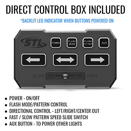
switch boxes do not interfere with the airbags, SRS wiring, or sensors. ... the wiring diagram to identify the Flash Pattern wire to manually run through.6 pages

Speed tech lights wiring diagram
Wiring Harness Diagram Wire ColorFunction Red*Positive Black* Negative BrownPrimary Speaker Brown Primary Speaker Grey Radio Rebroadcast * Indicates a main power cable. AUX Lighting Wiring Diagram Function Positive Red* Positive Cable 1 Blue Cable 2 White Cable 3 Green Cable 4 Orange Cable 5 Yellow Cable 6 NOTE: All AUX lighting cables contact ... 4 SpeedTech Lights, Inc 2019 Z -3 RILL SURFAC MOUNT Single Color Wiring Diagram Wire Color Function Red* Positive Black* Negative Yellow Flash Pattern Dual Color Wiring Diagram Wire Color Function Red* Positive Black* Negative Yellow Flash Pattern * Indicates a main power cable. Single Color Specifications Voltage 12 VDC Amps < 0.25 Optic TIR ... SpeedTech Lights, Inc. assumes no liability for any loss resulting from the use of this warning device. Proper installation is vital to the performance of the ...6 pages
Speed tech lights wiring diagram. According to earlier, the traces at a Speed Tech Lights Wiring Diagram represents wires. Sometimes, the wires will cross. However, it does not mean connection between the cables. Injunction of two wires is usually indicated by black dot in the intersection of two lines. There will be primary lines that are represented by L1, L2, L3, and so on. If you are not using the Grand Control Box, follow the wiring diagram to identify the Flash Pattern wire to manually cycle through patterns.6 pages Speed Tech Lights Wiring Diagram 12v relay wiring diagram spotlights giving them direct 12v they work fine so wiring relay issue i assumed the diagram i posted is the sure fire way of making sure the spotlights work briggs engine wiring diagram portal all terrain lawn i ve been asked about wiring alot recently so here is a diagram that should. Speed Tech Lights Wiring Diagram – wiring diagram is a simplified agreeable pictorial representation of an electrical circuit. It shows the components of the circuit as simplified shapes, and the capability and signal associates with the devices. A wiring diagram usually gives suggestion practically the relative position and settlement of ...
Speedtech Light Bar Wiring Diagram from www.diychatroom.com. Print the electrical wiring diagram off and use highlighters to trace the signal. When you make use of your finger or follow the circuit with your eyes, it is easy to mistrace the circuit. One trick that I actually 2 to print a similar wiring diagram off twice. 12' Light Bar Cable, 1.5' Power Cable, 8' AUX Cable. Flash Patterns. 29 Warning Patterns, 13 Traffic Advisor Patterns. Wiring Diagram. Wire Color. Function.8 pages Wiring Diagram Wire Color Function Red* Positive Black* Negative Yellow Flash Pattern * Indicates a main power cable. Wire Color Function White Positive (When bypassing Grand Control Box) Blue Super Take Down Green Take Down NOTE: All cables except Negative contact +12 VDC. Specifications Voltage 12 VDC Amps < 4.2 Optic TIR / Linear LED Count ... Improper wiring and mounting of the warning device will ... To ensure that this doesn't happen to you, Light ... AUX Lighting Wiring Diagram. Wire Color.5 pages
switch boxes do not interfere with the airbags, SRS wiring, or sensors. ... the wiring diagram to identify the Flash Pattern wire to manually run through.6 pages 4 SpeedTech Lights, Inc 2020 Z- TIR GRILLE / SURFACE MOUNT Wiring Diagram Wire Color Function Red* Positive Black* Negative Yellow Flash Pattern * Indicates a main power cable. Specifications Voltage 12 VDC Amps < 0.37 Optic TIR LED Count 4 Cable Length 1’ Flash Patterns 24 Wire Color Function Green Steady Burn Override White Sync (Max 8 Units) Speed Tech Light Bar Wiring Diagram. To properly read a cabling diagram, one has to know how typically the components inside the method operate. For example , when a module will be powered up and it sends out a new signal of half the voltage plus the technician would not know this, he'd think he offers an issue, as this individual would expect ... SpeedTech Lights, Inc. assumes no liability for any loss resulting from the use of this warning device. Proper installation is vital to the performance of the ...6 pages

Sign Ballasts Smart Wire Parallel Wire Keystone Technologies
4 SpeedTech Lights, Inc 2019 Z -3 RILL SURFAC MOUNT Single Color Wiring Diagram Wire Color Function Red* Positive Black* Negative Yellow Flash Pattern Dual Color Wiring Diagram Wire Color Function Red* Positive Black* Negative Yellow Flash Pattern * Indicates a main power cable. Single Color Specifications Voltage 12 VDC Amps < 0.25 Optic TIR ...
Speedtechlights Com
Wiring Harness Diagram Wire ColorFunction Red*Positive Black* Negative BrownPrimary Speaker Brown Primary Speaker Grey Radio Rebroadcast * Indicates a main power cable. AUX Lighting Wiring Diagram Function Positive Red* Positive Cable 1 Blue Cable 2 White Cable 3 Green Cable 4 Orange Cable 5 Yellow Cable 6 NOTE: All AUX lighting cables contact ...
Speedtech Lights Striker Tir 6 Head Led Traffic Advisor Import It All

Spa Pack Troubleshooting Pool Spa News

17 99 Civic Engine Harness Wiring Diagram Engine Diagram Wiringg Net

Wiring How To Wire 1 Phase 3 Speed Motor Electrical Electric Fan Ac Fan Motor Ac Fan
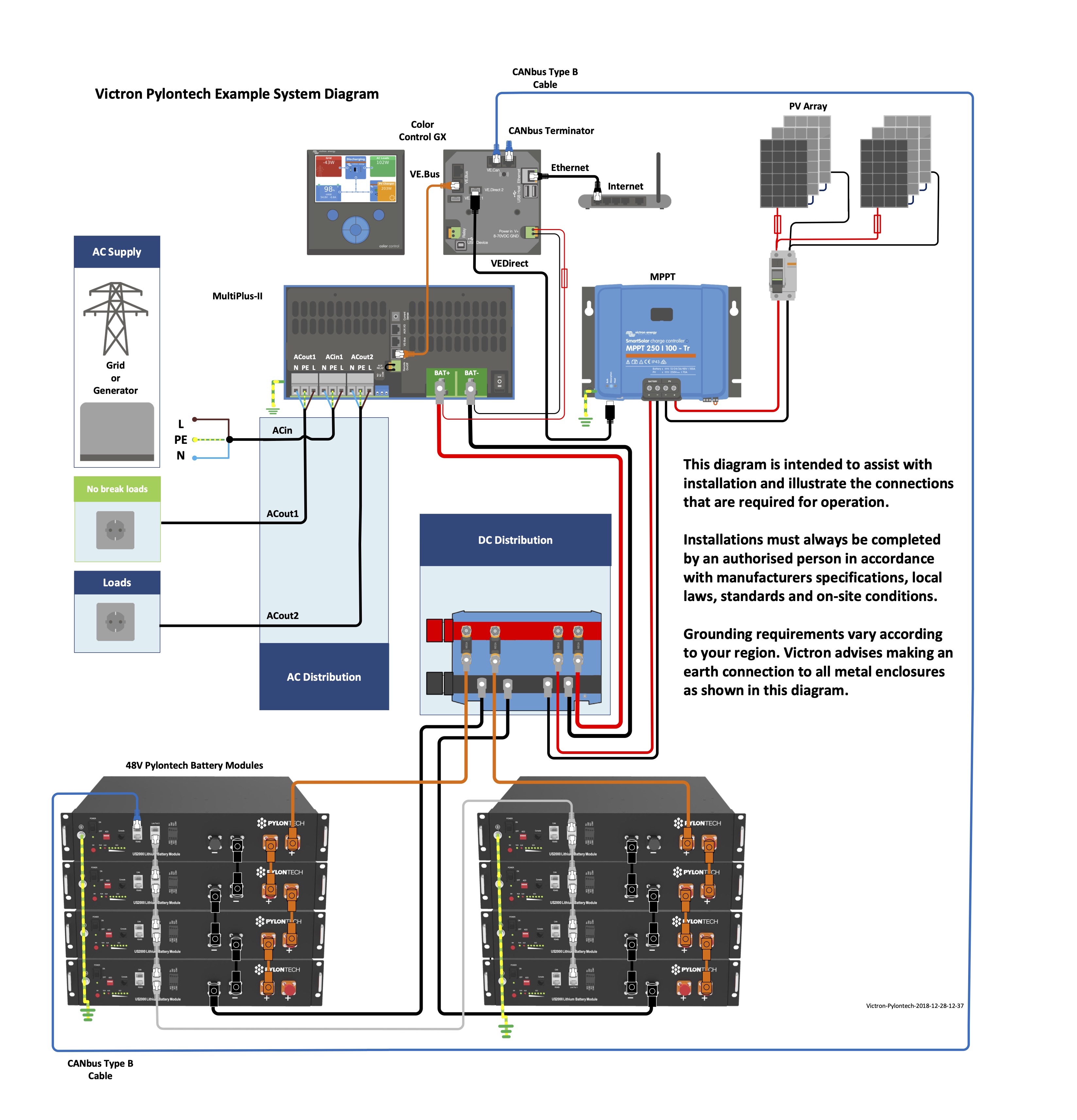
Victron Pylontech Up2500 Us2000 Us3000 Us2000c Us3000c Up5000 Phantom S Force L1 L2 Victron Energy
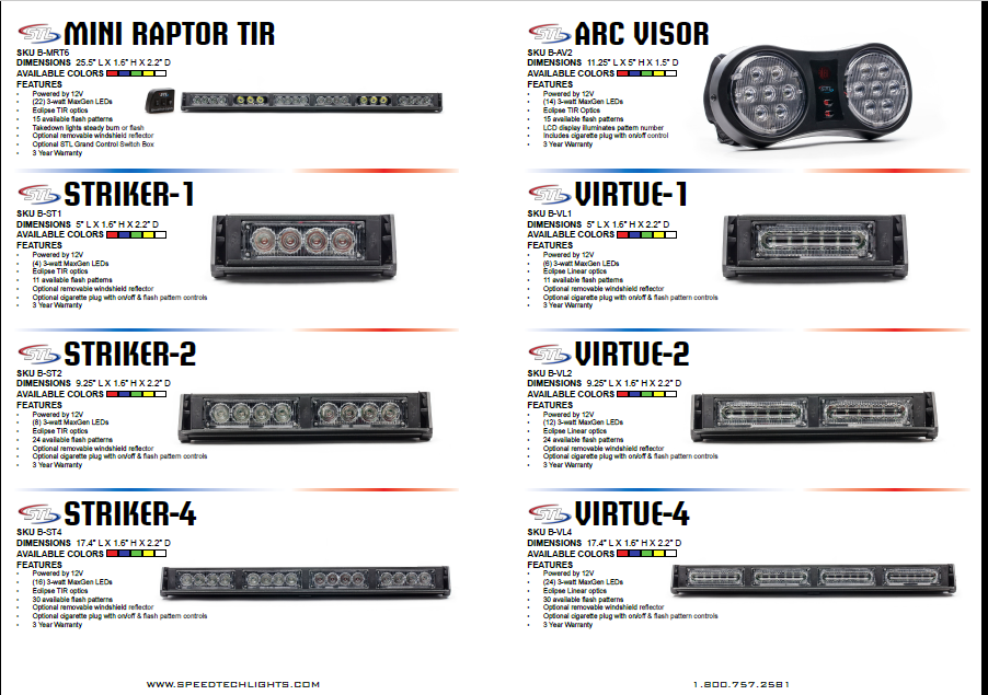
Catalog Speedtech Lights
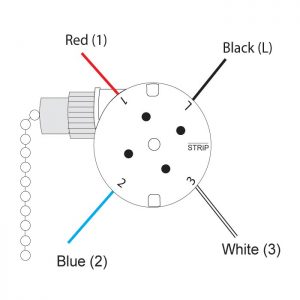
Ceiling Fan Switch Compatibility Guide Ceilingfanswitch Com

Speed Tech Lights For Sale Ebay

Catalog Speedtech Lights

Amazon Com Curt 56130 Non Powered 3 To 2 Wire Splice In Trailer Tail Light Converter 4 Pin Wiring Harness Automotive
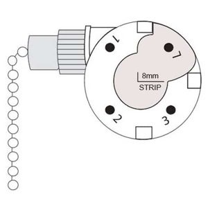
Ceiling Fan Switch Compatibility Guide Ceilingfanswitch Com

Pin On Led Light Bar Wiring

The Blog Drinker S Lighter Blog Speedtech Lights Wiring Diagram

I Need Wiring Diagram Colors For Transmission Speed Sensor On A Isuzu Vehicross 1999
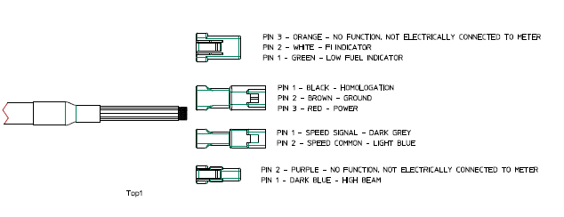
Stock Dash Replacement With Trail Tech Voyager Pro Ktm 2 Stroke Thumpertalk

Amazon Com Led Light Bar Wiring Harness 4wdking 14awg 2 Lead 400w 12ft Length Heavy Duty 40amp Fuze Relay Waterproof Switch Light Bar Accessories
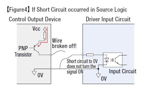
Control Basics The Difference Between Sink And Source Logic

1972 Nova Resurrexion Speedtech Performance Usa

There S Only One Blog Speedtech Light Bar Wiring Diagram
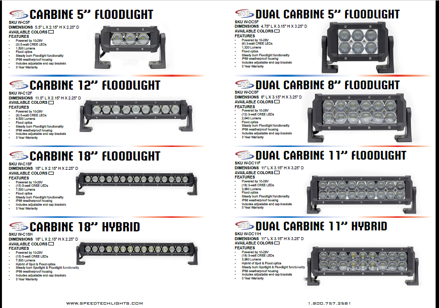
Catalog Speedtech Lights

Speedtech Lights Super Take Down Raptor Tir Upper Windshield Interior Split Led Strobe Visor Light Bar For Hazard Emergency Vehicle Warning Flashing Std W Control Box Red Blue Clear Buy Online In South

94 95 Mustang Headlights And Fog Lights Wiring Diagram In 2021 Led Mirror Bathroom Bathroom Mirror Lights Headlights
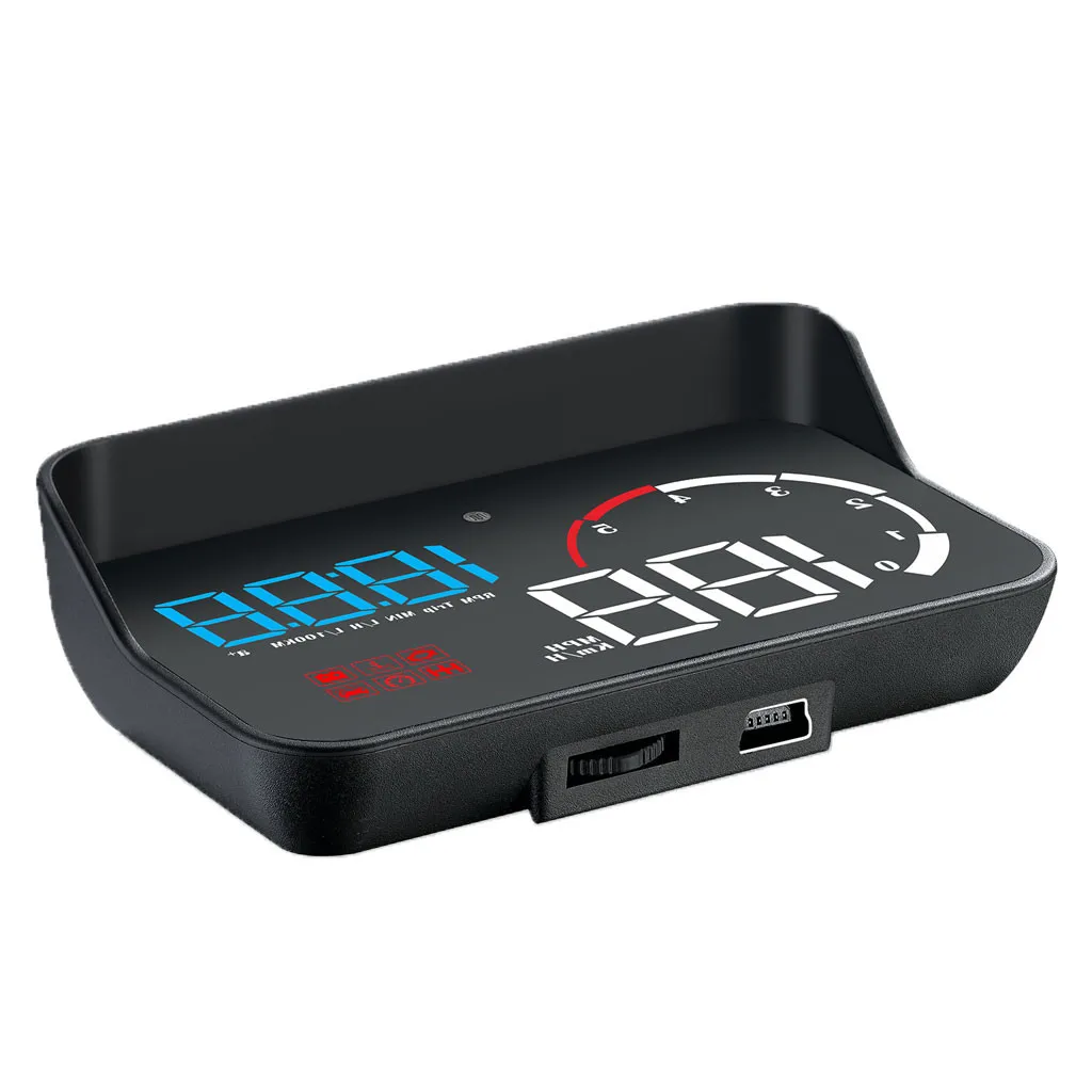
M10 Mobil Hud Obd2 Digital Mobil Hud Led Head Up Display Overspeed Speedometer Kabel Alarm Dengan Anti Slip Mat Universal Zer Kepala Up Display Aliexpress

Buy Super Take Down K Force Tir 47 Full Size Led Police Light Bar For Warning Vehicles Roof Mount Emergency Strobe Lights Blue Green Online In Vietnam B078fqjw94
Speedtechlights Com
There S Only One Blog Speedtech Light Bar Wiring Diagram

Top 10 Best Speedtech Light Bar Wiring Diagramin 2021 Reviews Ratings

Top 10 Best Speedtech Light Bar Wiring Diagramin 2021 Reviews Ratings
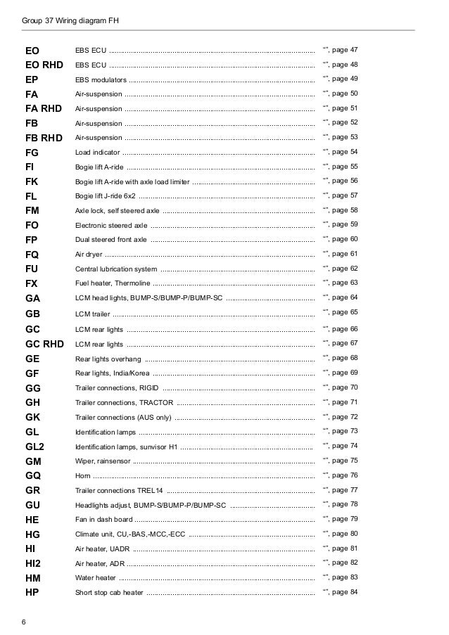
Volvo Wiring Diagram Fh

Buy Speedtech Lights Striker Tir 6 Head Led Traffic Advisor Windshield Mount Strobe Light Bar For Emergency Vehicles Hazard Warning Directional Flashing W Cig Plug Control Box Amber Amber Online In Indonesia B078fn37f4

How Do I Wire Lights For Constant Operation Smart Vision Lights

Speedtech Spotlight How To Connect Lights To Aux Youtube
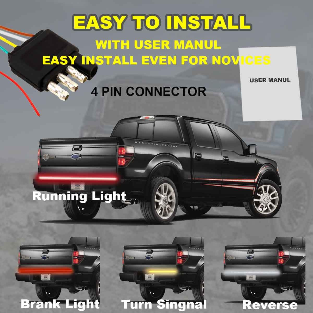
Accent Off Road Lighting Light Lighting Accessories Weatherproof No Drill Install 60 Triple Led Tailgate Light Bar W Sequential Red Turn Signal Led Solid Beam Full Function Reverse Brake Running Adpcosmetics Com

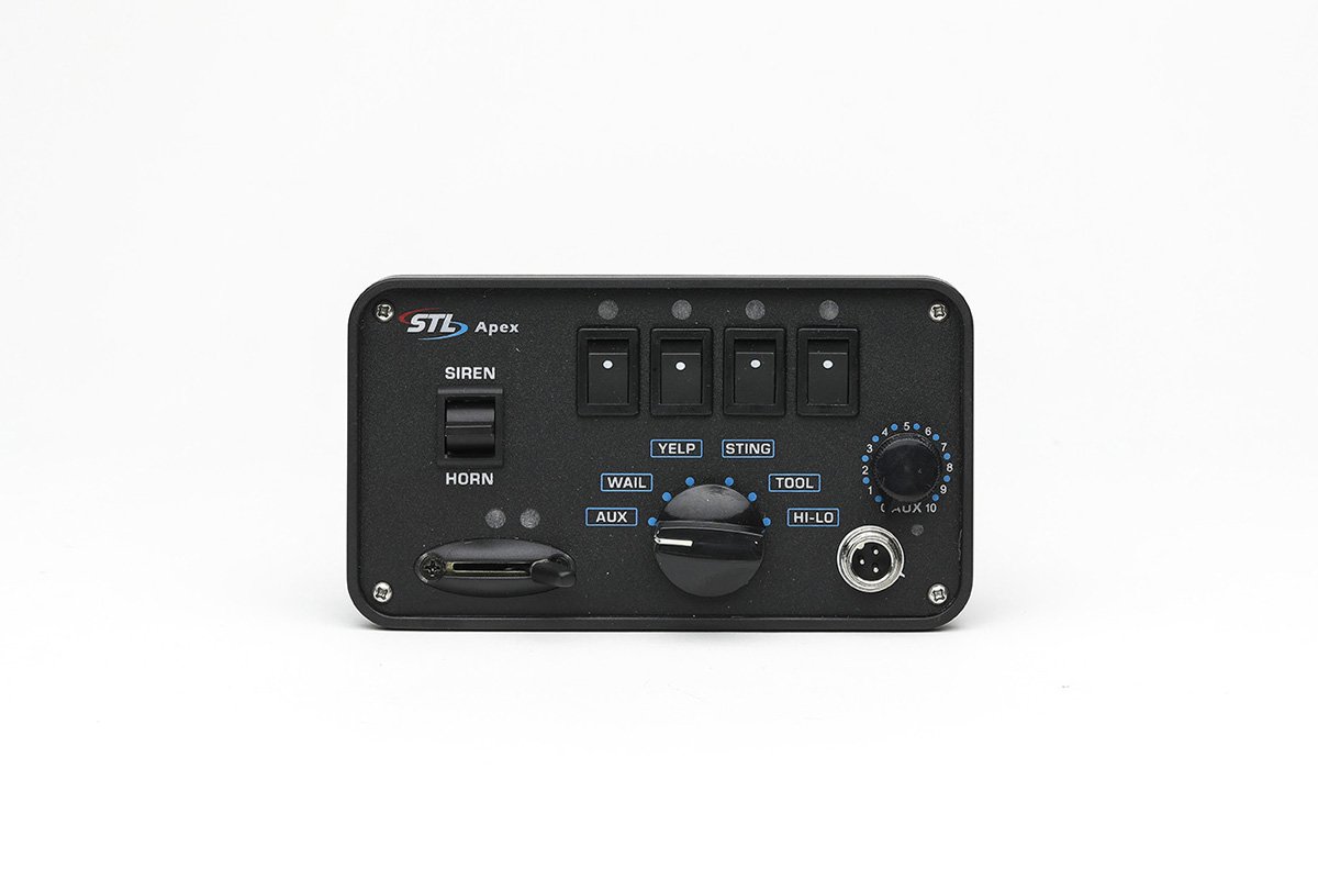
Stl Boss 200 Dual Tone Siren From Speed Tech Lights Youtube

99 Civic Engine Harness Wiring Diagram And Engine Tuning Solutions Tech Area Phearable In 2021 Ecu Honda Civic Diagram
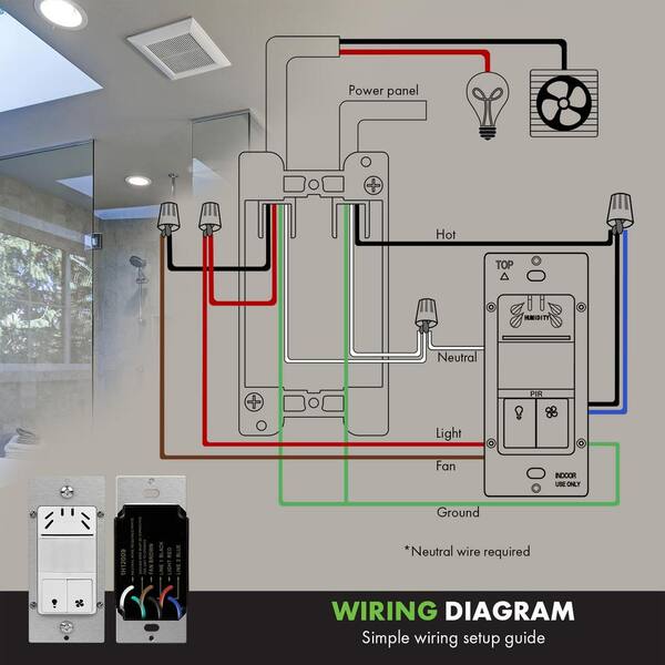
Topgreener 3 Amp 3 Speed Dual Tech Humidity Sensor Switch Bathroom Light And Fan Control In White Tdhos5 W The Home Depot
0 Response to "38 speed tech lights wiring diagram"
Post a Comment