41 block diagram reduction rules
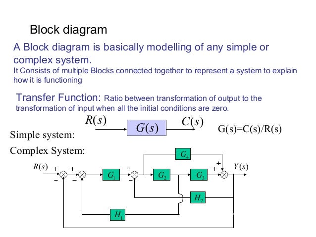
Block diagram reduction technique . Because of their simplicity and versatility, block diagrams are often used by control engineers to describe all types of systems. A block diagram can be used simply to represent the composition and interconnection of a system. Block Diagram • It represents the structure of a control system. • It helps to organize the variables and equations representing the control system. It is composed of: • boxes, that represents the components of the system including their causality; • Lines with arrows, that represent the actual
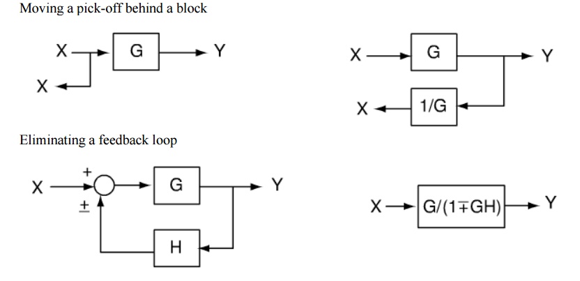
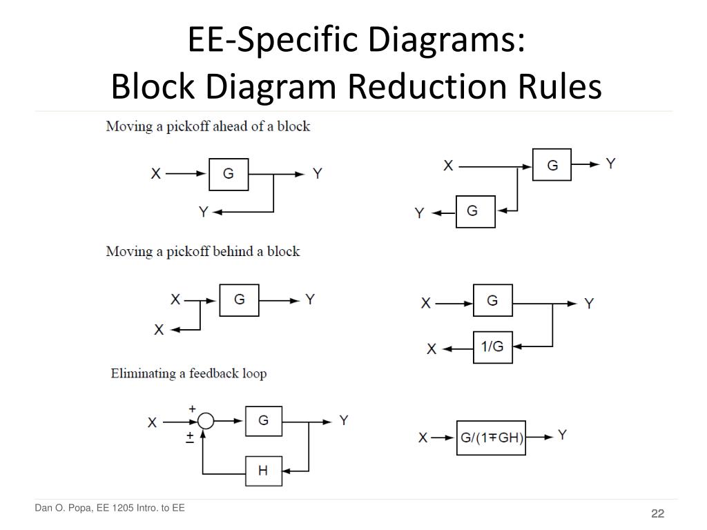
Table 1: Block Diagram Reduction Rules Table 2: Basic rules with block diagram transformation . Example 1: Example 2: Example 3: Example 4: Example5: ECE 680 Modern Automatic Control Routh’s Stability Criterion June 13, 2007 1 ROUTH’S STABILITY CRITERION Consider a closed-loop transfer function H(s) = b 0sm +b
Block diagram reduction rules
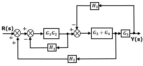
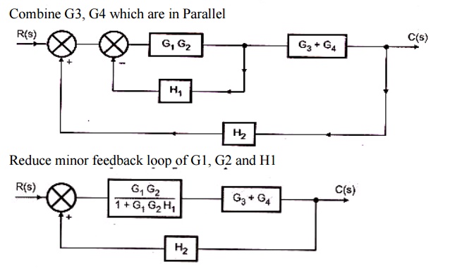
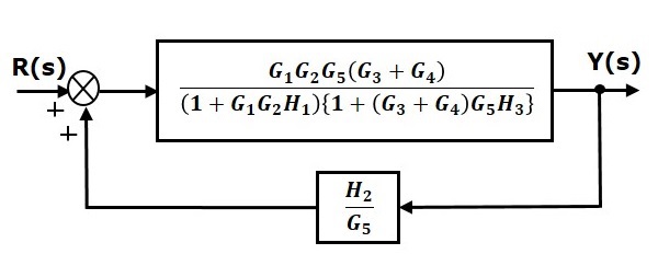
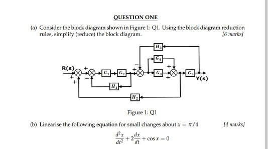
Let us simplify (reduce) this block diagram using the block diagram reduction rules. Step 1 − Use Rule 1 for blocks G 1 and G 2. Use Rule 2 for blocks G 3 and G 4. The modified block diagram is shown in the following figure. Step 2 − Use Rule 3 for blocks G 1 G 2 and H 1. Use Rule 4 for shifting take-off point after the block G 5. Hence for the reduction of a complicated block diagram into a simple one, a certain set of rules must be applied. Here in this section, we will discuss the rules needed to be followed. Rules for Block Diagram Reduction. So, one by one we will discuss the various rules that can be applied for simplifying a complex block diagram. Block Diagram Reduction Figure 1: Single block diagram representation Figure 2: Components of Linear Time Invariant Systems (LTIS)
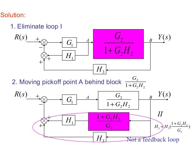
Block diagram reduction rules. Block Diagram Reduction W.3 4Mason™s Rule and the Signal-Flow Graph A compact alternative notation to the block diagram is given by the signal-⁄ow graph introduced Signal-⁄ow by S. J. Mason (1953, 1956). As with the block diagram, the signal-⁄ow graph o⁄ers a visual tool for graph Welcome to our process flow diagram symbols list. Scroll down and use the table of contents on the left to navigate this page and see the different symbol types most commonly used by engineers. But first, let’s review the purpose and benefits of a PFD. Block Diagram Reduction Rules. The system has a proportional controller with a variable gain K. 1 Current Shunt. For (b) and (c), also calculate the damping ratio, ζ, and natural frequency, ω n. 51, Using The Ideas Of Block-diagram Simplification The Special Structure In Fig 3. Reduction of the block diagram shown in Figure 3-44. Figure 3-46 Block diagram of a system. Solution. The block diagram of Figure 3-44 can be modified to that shown in Figure 3-45(a). Eliminating the minor feedforward path, we obtain Figure 3-45(b), which can be simplified to
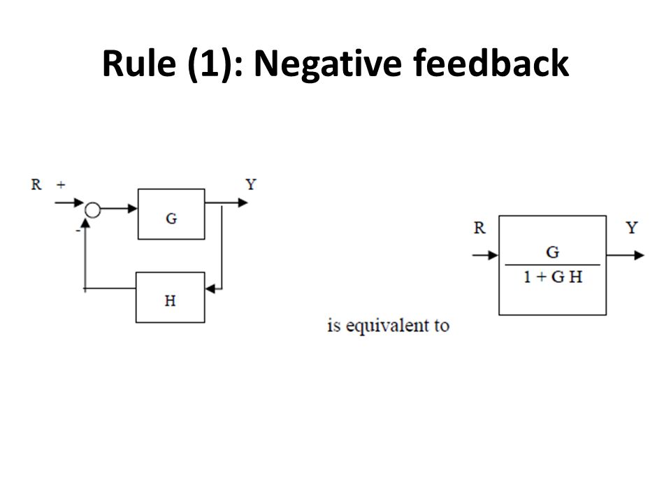
Using Block Diagram PcmchonaJ opera.}ion system can be obs ente.d performance be obhejne.d uge.ð analysis 4 desi9n ok control syseern +0 construcå block diagrams complico±eA and sys+ems. DiSaAfQn+eges Block digra.m - not unique sources enegy the sys+em are nay shown in dìQ9TQrn. Ln procedure re-dudion block there is no check Run&ìons which The diagram will then be simplified through a process that is both graphical and algebraic. For exam-ple, equivalent blocks for a negative feedback loop are shown in Figure 8.9, along with an algebraic proof. Figure 8.9 A negative feedback block reduction Other block diagram equivalencies are shown in Figure 8.10 to Figure 8.16. In all May 04, 2021 · Line Diagram. It is a simplified notation of an electrical system, also called as One-Line Diagram or Single Line Diagram. It is similar to the block diagram except that various electrical elements such as transformers, switches, lights, fans, circuit breakers, and motors are represented by standard schematic symbols.. It consists of symbols to represent the components and lines to … We notice that the first Oct 12, 2018 · Let us simplify (reduce) this block diagram using the block diagram reduction rules. Consider the block diagram shown below: If the transfer function of the system is given by T(s)=G1G2+G2G3/1+X. Start programming with Function Blocks and explore the world of standard and custom function blocks.
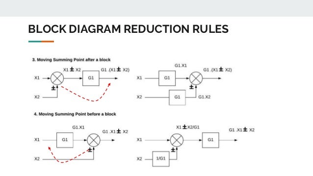
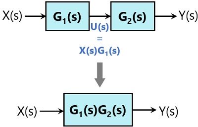
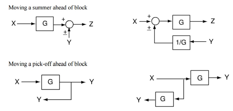
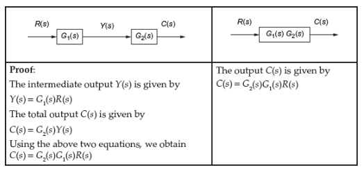
Block diagram transfer function calculator 2.1 Rules for Block Diagram Reduction: Now the following block diagram algebra is often used to describe rules for reduction: Rule 1: Blocks in cascade Two or more blocks in cascade may be combined in one block. Rule 2: Combining Blocks in Parallel Two blocks or more in parallel may be combined in one block as the algebraic sum. X(G 1 (s) G X(s ... Block Diagram Reduction Figure 1: Single block diagram representation Figure 2: Components of Linear Time Invariant Systems (LTIS) Hence for the reduction of a complicated block diagram into a simple one, a certain set of rules must be applied. Here in this section, we will discuss the rules needed to be followed. Rules for Block Diagram Reduction. So, one by one we will discuss the various rules that can be applied for simplifying a complex block diagram.
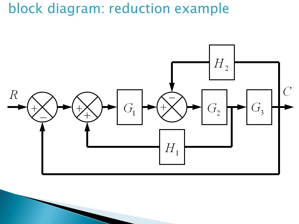
Let us simplify (reduce) this block diagram using the block diagram reduction rules. Step 1 − Use Rule 1 for blocks G 1 and G 2. Use Rule 2 for blocks G 3 and G 4. The modified block diagram is shown in the following figure. Step 2 − Use Rule 3 for blocks G 1 G 2 and H 1. Use Rule 4 for shifting take-off point after the block G 5.

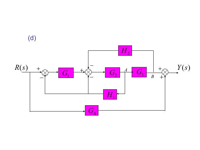
Simplify Reduce This Block Diagram Using The Block Diagram Reduction Rules Show All Steps G4 R S Homeworklib

Block Diagram Models Block Diagram Manipulation Diagram Models Signal Flo W Gra Phs And Block Diagram Reduction Control 3b Pdf Author Lavi Shpigelman Pdf Document













0 Response to "41 block diagram reduction rules"
Post a Comment