41 pad mount transformer wiring diagram
ACME ELECTRIC U MILWAUKEE, WI U 800.334.5214 U acmetransformer.com 125 GENERALGENERAL ELECTRICAL CONNECTION DIAGRAMSACME® TRANSFORMER™ WIRING DIAGRAMS PRIMARY: 240 Volts Delta SECONDARY: 208Y/120 Volts TAPS: 2, 5% BNFC X1 H1 X2 X3 H2 H3 X0 3 2 1 3 2 1 3 2 1 ConnectConnect Primary Primary Inter- Secondary Pad Mount Transformer Wiring Diagram. Collection of pad mount transformer wiring diagram. A wiring diagram is a streamlined standard pictorial depiction of an electrical circuit. It shows the parts of the circuit as streamlined forms, as well as the power and also signal connections in between the gadgets. A wiring diagram usually gives info regarding…
Pad Mount Transformer Wiring Diagram Luxury Nih Standard Cad Details Just what is a Wiring Diagram? A Beginner s Overview of Circuit Diagrams. A very first consider a circuit diagram might be complicated, however if you could read a subway map, you could review schematics. The purpose coincides: getting from factor A to aim B. Literally, a ...

Pad mount transformer wiring diagram
Single-phase pad-mounted ranch runner transformer Product Scope: kVA: 10-50 Primary Voltage: 2400-14,400 V Secondary Voltage: 120-600 V B C A 16" (19" for 150 kV BIL) H1A H1B X1 X2 X3 B C 30" 16" (19" for 150 kV BIL) H1A H1B X1 X2 X3 Figure 2. Single-phase pad-mounted Shrubline. Figure 3. Single-phase pad-mounted MaxiShrub. Figure 4. Single ... precast transformer fndn. w/7'x 7'top rod, ground , 1/2" x 8' clamp, ground rod wire, •4 solid copper, bare connector, tap, vise type, •4 solid copper metering duct, metallic, 11/2 " min. i.d. bushing insulated • as required for 480y / 277v low volt age ratings only suppled by customer transformers are specifically designed for commercial and residential applications, such as hotels, hospitals, universities, among others. Our transformers are designed for outdoor installation with cabinets meeting C57.12.34 & C57.12.28. Prolec GE Three-Phase Pad-Mounted Transformers use aluminum or copper windings and are optimized
Pad mount transformer wiring diagram. transformer service entrance panelboard d g e f n b c typical pad mount transformer service entrance. title: 26200001 - service entrance transformer wiring diagram-default created date: 4/14/2014 10:24:51 am ... Single-phase pad-mounted ranch runner transformer Product Scope: kVA: 10-50 Primary Voltage: 2400-14,400 V Secondary Voltage: 120-600 V B C A 16" (19" for 150 kV BIL) H1A H1B X1 X2 X3 B C 30" 16" (19" for 150 kV BIL) H1A H1B X1 X2 X3 Figure 2. Single-phase pad-mounted Shrubline. Figure 3. Single-phase pad-mounted MaxiShrub. Figure 4. Single ... The wiring diagram provides details of any control, fan and alarm wiring that may have been supplied. Lifting and Handling Lifting hooks are provided near the top of the transformer tank for lifting. All four lifting hooks must be used simultaneously. The transformer must not be lifted from any points other than the provided lifting hooks. mounted vertically. Transformers must never be mounted next to or above heat generating equipment. Grounding Ventilated core and coil assemblies are solidly grounded to the enclosure. On units equipped with electrostatic shields, the shields are grounded to the core. Encapsulated units have a ground stud located in the wiring compartment.
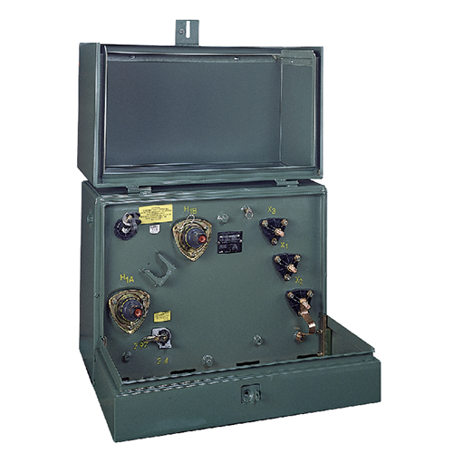
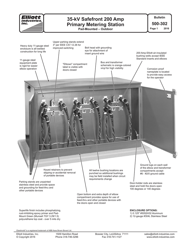
2. This document shows ordering information, dimensions, and arrangements of S&C pad-mounted switchgear for three-phase, 12 kV, 17 kV, and 21 kV installations. Pad-mounted switchgear have a maximum voltage rating of either 14.4 kV or 25 kV. The switchgear include externally operable, three-phase, gang-operated switches and/or Type E power fuses. About Press Copyright Contact us Creators Advertise Developers Terms Privacy Policy & Safety How YouTube works Test new features Press Copyright Contact us Creators ... Single Phase Pad Mounted Distribution Transformer ERMCO single phase pad mounted distribution transformers are designed and manufactured in compliance with all applicable IEEE and RUS standards. All transformers are oil filled, 65°C rise, and designed for usual service conditions per IEEE C57.12.00. Pad-mount transformers are (nearly always) oil-filled units and so must be mounted outdoors only. The core and coils are enclosed in a steel oil-filled tank, with terminals for the transformer accessible in an adjacent lockable wiring cabinet.
Pad Mount Transformer Wiring Diagram Luxury Nih Standard Cad Details Forums Tesla Coils DRSSTC current transformer questions 4hv Building wiring diagrams reveal the approximate locations and also affiliations of receptacles, illumination, and irreversible electric services in a building. Fusing and circuit breaker protection. How to overcurrent protect 600 Volt class transformers and associated wiring per NEC 450.3 (B), NEC 240.3 and NEC 240.6 (A). 1. Primary protection only is required if the transformer is single-phase and the secondary has only two wires. Overcurrent protection rating and location are shown in Diagram A ... pad mount transformer wiring diagram - Building electrical wiring representations reveal the approximate places and interconnections of receptacles, lights, and irreversible electrical services in a building. Size: 270.72 KB. Dimension: 1275 x 1650. DOWNLOAD. Wiring Diagram Sheets Detail: Name: pad mount transformer wiring diagram - Top Pad Mount Transformer Wiring Diagram Single Phase Pole Mounted Transformer Wiring Diagram Wiring. File Type: JPG. Source: michaelkorsbagoutlet.us. Size: 31.57 KB. Dimension: 250 x 200.
Name: control transformer wiring diagram - pad mount transformer wiring diagram Collection of E 60 05 Isolated Ground Receptacle Wiring Diagram DOWNLOAD Wiring Diagram. File Type: JPG. Source: metroroomph.com. Size: 332.46 KB. Dimension: 1275 x 1650. See also Baldor 1.5 Hp Wiring Diagram Gallery.
Figure 1. Three-phase pad-mounted compartmental type transformer. LOW-VOLTAGE BUSHING SUPPORT SILL Suitable for skidding, rolling, and jacking 5-position tap changer Ground pad and strap for x Parking stand 0 Liquid level gauge Nameplate laser-scribed anodized aluminum Removable cabinet walls Drip shield Type Three Phase, 50 or 60 Hz, 65 ºC Rise
This test is performed on all transformers to verify transformer circuit and component integrity. This test is performed with an ohmmeter to verify that the internal wiring is correct. The transformer's nameplate is compared to manufacturing information for style, serial number, kVA, HV rating, LV rating, tap
Phase Pad-Mounted distribution transformers that meet applicable ANSI®/IEEE® standards. With high voltages up to 34.5 kV and ratings up to 5,000 kVA (ONAN), Prolec GE compartmental-type Three Phase Pad-Mounted Commercial Transformers are designed for outdoor installation on a concrete pad and provide underground power distribution to commercial,
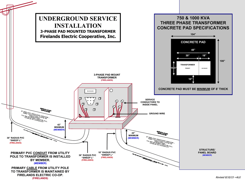
FIGURE 1 Service Installation Diagram - Three Phase Padmounted Transformer FIGURE 2 Three Phase Padmounted Transformer Required Clearances ... nature) to feed a Company owned outdoor three phase pad-mounted transformer, or transformer(s) located within a vault. It does not apply in a network area, or in URD / UCD ...
Study the wiring diagram of the pad mount carefully though, many pad-mounts will have the neutrals bonded to the tank wall internally. Make sure the neutral from the secondary winding is separate from the primary winding neutral (the two are not connected together internally) and that the secondary neutral is brought out via a fully insulated ...
62. 31 4004 Rev. E - Substation Standards Transformer Sudden Pressure Relay Schematic Diagram 63. 31 4005 Rev. D - Substation Standards Duplex Switchboard Panel Wiring Diagram and Cabling Methods 64. 31 4008 Rev. C - Substation Standards Mimic Bus Color Standard 65.
New, rewired, altered, or repaired wiring installations intended for connection to the Company's distribution system shall comply with the rules of the Company, the National Electrical Code ®, and any other codes or regulations in effect in the area served.
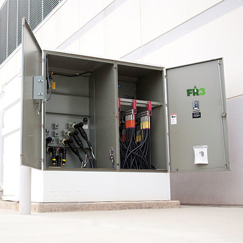
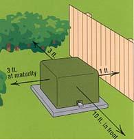
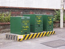
Padmount Transformer. A padmount transformer is a ground-mounted utility distribution transformer, which usually is housed in a locked metal cabinet, situated on a small concrete pad. These distribution transformers are normally located in residential subdivisions. Since all of the live contact points are enclosed in a grounded metal box, this ...
connections, and weights. The transformer wiring diagram provides details of any control, fan and alarm wiring that may have been provided. Lifting and Handling Lifting lugs or bosses are provided to lift the completely assembled transformer. All lifting lugs or bosses must be used simultaneously to provide a safe, balanced lift.
connections to the transformer as specified in Sections IV and V. Section II: Concrete Footing, Foundation and Pad Installation 1. The customer shall furnish, install, own and maintain the concrete footing, foundation, pad, ground rods and all wiring. Reference: Illustration #1 - page 4. 2.
transformers are specifically designed for commercial and residential applications, such as hotels, hospitals, universities, among others. Our transformers are designed for outdoor installation with cabinets meeting C57.12.34 & C57.12.28. Prolec GE Three-Phase Pad-Mounted Transformers use aluminum or copper windings and are optimized
precast transformer fndn. w/7'x 7'top rod, ground , 1/2" x 8' clamp, ground rod wire, •4 solid copper, bare connector, tap, vise type, •4 solid copper metering duct, metallic, 11/2 " min. i.d. bushing insulated • as required for 480y / 277v low volt age ratings only suppled by customer
Single-phase pad-mounted ranch runner transformer Product Scope: kVA: 10-50 Primary Voltage: 2400-14,400 V Secondary Voltage: 120-600 V B C A 16" (19" for 150 kV BIL) H1A H1B X1 X2 X3 B C 30" 16" (19" for 150 kV BIL) H1A H1B X1 X2 X3 Figure 2. Single-phase pad-mounted Shrubline. Figure 3. Single-phase pad-mounted MaxiShrub. Figure 4. Single ...









0 Response to "41 pad mount transformer wiring diagram"
Post a Comment