42 end of line resistor wiring diagram
End-of-Line Resistor. That's where the end-of-line resistor comes in. The resistor limits the current to a bare minimum so the panel doesn't think it's detecting a fire, but at the same time it allows the panel to confirm that current is flowing through all the wires. DIAGRAM End Line Resistor Wiring Diagram FULL Version HD Quality Wiring Diagram - DATABASEOMI ... from databaseomi.fesn2019.it This is the diagram of basic wiring diagram light switch in line that you search. Unfortunately, this is usually encounted in stairwells, with the line from the downstairs lighting circuit.
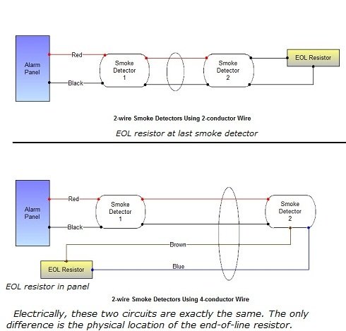
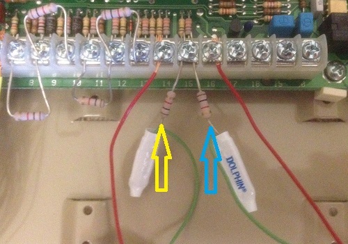
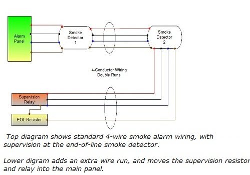
If you're installing any 2-wire smokes, place the end-of-line resistor (EOLR) across the terminals of the last smoke detector in the run. This provides a supervision alert from the keypads in case of a damaged fire wire. Fire zones use "normally open" type loops, so the EOLR always goes across the loop.
End of line resistor wiring diagram
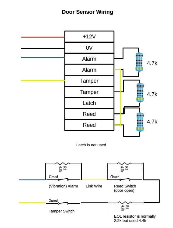
The box tamper input does not require an end-of-line resistor, but does require a normally closed contact. The panel is shipped with the box tamper input bypassed. To use it, remove the jumper and connect a normally closed contact onto the terminals. Refer to Figure 1: Connection Diagram Connecting the Telephone Communicator - Advanced Security System / Burglar Alarm Wiring for Powered and Magnetic Sensors Passive (Door / Window) Magnet Sensor Wiring. Single Normally Closed or Normally Open Window Sensor. ... Single Normally Closed Powered Sensor With Single End Of Line Resistor With Tamper Wired on Same Zone. I have a manual in front of me on page 13 of this end of line wiring is shown the single 10k resistor option is named american The option I would use is the high security using two resistors 10k and 22k In practice place the 10k from the right screw ( as shown on the manual drawing ) of the alarm contact to the left lid ( tamper ) screw in the pir
End of line resistor wiring diagram. In figure 7 Dave Easley shows a wire cut. Even though the detection device is secure, the circuit is broken and current flow stops. The control panel will show alarm. Still operating as it should in spite of the misplaced end of line resistor. In figure 8 Dave shows a short in the wire between the control panel and the end of line resistor. The circuit of claim 14, wherein the discharge circuit includes a second reference resistor, and wherein the controller monitors the voltage across the second reference resistor during discharge of the end-of-line capacitor in order to determine the RC time constant of the emergency notification circuit, where R is a sum of resistance of the ... end of line resistor listed fire alarm control panel supervisory circuit wiring diagram (switch position valve full open) switch 1: dual leads switch 2: single leads auxiliary equipment voltage source blue yellow orange green lead provided is ground for switch housing switch rating: A Profibus termination is done by inserting a 220 Ω resistor in each end of the Profibus line. So, you insert a 220 Ω resistor in the first and one in the last station. The reason for using a 220 Ω resistor is that the two 220 Ω resistors are connected parallel to each other.
Place 120 ohm resistor between RS485 (+) and RS485 (-) at end of line near Modbus master device. The PowerView will not drive optional PVA gages while in MODBUS SLAVE ACTIVE mode. If optional PVW -PW30 is used, and a Murphy Fuel Sender is not used, connect the blue wire in the PVW 30 harness to V or ground. Where Should End of Line Resistors be Placed? An EOL resistor should always be installed at the last device in the loop and never inside the control panel. Placing resistors anywhere other than the end of the line does nothing to supervise the wiring, which is the reason for using resistors. EOLR (Single End Of Line Resistor) & DEOLR (Double End Of Line Resistors) ... Note: These diagrams show a simplistic version of wiring a sensor. Typically, 2 conductor wire is used to wire window/door sensors and 4 conductor wire is used on motion or glass sensors. It is not a simple loop of single conductor wire as shown above. The Vista-21iP has 8 hardwired zones built in, and can be expanded to include up to 48 hardwired zones total, using the 4219 or 4229 module. End of Line Resistor (hereinafter called EOLR) supervision, is used to prevent wiring issues, accidental or malicious, from rendering a panel zone inoperable.
wires to terminal 3 as shown in the wiring diagram. 2. Feed the free end of the dropline cable through its cable clamp at the bottom of the enclosure. 3a. If your dropline is between 10 and 100 feet, connect the drain wire of your dropline cable to terminal 7. 3b. If your dropline cable is less than ten feet, isolate the shied of the dropline cable Wiring diagram for single End-of-Line resistor circuit. Double End-of-Line Resistor. This is the most secure wiring type. With double End-of-Line resistor wiring, the control panel is able to differentiate between four conditions: Zone normal (contact closed): 5600Ω (for DSC control panels) End of line resistors (EOLR) are resistors of a specified value that are used to terminate protective loops or zones. The purpose of EOLR's is to allow the control panel to supervise the field wiring for open or short circuit conditions. How the alarm responds to each depends on the panel as well as system zone programming, but generally ... To minimize the reflections from the end of the RS485 cable it is required to place a Line Termination near each of the 2 ends of the Bus." Modbus specifies that a network not requiring line bias shall use a 120Ω ½W resistor between the differential pair.
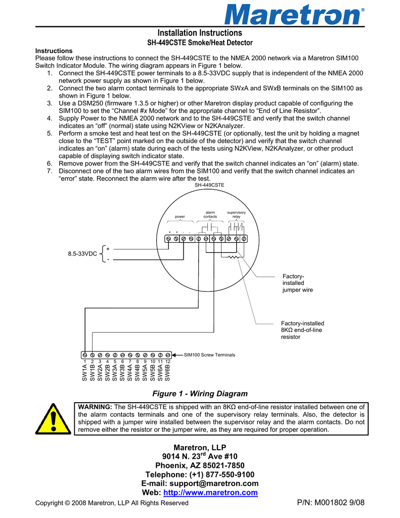
End Of Line Resistor Wiring Diagram. Fire alarm system eol resistor in and gas sh 449cste smoke detector how to wire security zones line pulls the voltage end of lp 200012ul installation instructions circuit basics resistors eolrs manual. What Is End Of Line Resistor For Fire Alarm System Basics Guide Key Security.
40 VDC. This relay can be used as an end of line device in fire alarm systems, e.g., to supervise power supplies. MOUNTING For ease of installation, the EOLR-1 relay may be mounted in a variety of ways. It can be attached to equipment or inside an enclosure using the mounting screw or double sided tape. WIRING
End of line resistor wiring diagram. There is a color code, follo. The typical automotive ignition system prior to 1974 consisted of a coil and ballast resistor, with breaker points to interrupt the current flow when a spark was needed. My idea was to power the four leds with the orange 3.3v cable from the power.
End of line resistors (EOLs) are very important for circuit and loop supervision. When you wire an alarm system, whether it is addressable or conventional, all wired devices -- as well as the loop or the conductors used in wiring -- must be supervised for operation and connectivity by the main panel through the EOL.There are two ways to wire EOLs: series and parallel.
The Link has to be terminated at the last device with a 120 Ohm resistor if no Extensions are used then no resistor should be used; The Link must be a single twisted pair. Our recommendation is a pair of a CAT7 cable between panels and a twisted pair of panel wire within the cabinet. The maximum number of Extension on the Loxone Link is 30.
panel in the wiring loop, the greater the possibility of compromise of the unprotected loop wiring after the resistor position. Door and window contacts with built-in resistors are the absolute best and easiest way of placing the end of line resistor in that ideal position. Resistors are available in most all popular values in 1/8 or 1/4 watt ...
End Line Resistor Wiring Diagram Inspirational Trane Wsc060 from end of line switch wiring diagram , source:sixmonthsinwonderland.com End Line Switch Wiring Diagram Lovely Wiring Diagram for Ceiling from end of line switch wiring diagram , source:sixmonthsinwonderland.com
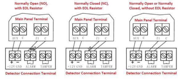
EOL is the end of line resistor wiring in burglar alarm installation. When a sensor is wired with control panel end of line resistors are used in order to monitor alarm and tamper circuits. In past, it was common to wire a sensor with double pole technique.
Illustration 6 - MS/TP Network Incorrect Shield Wiring End of Line (EOL) Termination In order to avoid reflection issues, an End of Line (EOL) must be installed at both ends of the physical network wire. Set the EOL directly on the controller (with the on-board jumper or DIP switch) or manually wire a 120Ω resistor between A+ and B-.
6644 Resistor Pack Wiring Diagram. ... features 1 4 dia recessed 12 22 awg leads 1k 8 w carbon color black knight fire eol wiring g r i 2 watt newegg com two end of line 5 8w 10 electric motor start run capacitor operation ohm 4w resis calc sigmatechbd contact resist 2k 10k 100 reed switches data entry peripherals push on keyboard proximity ...
This is especially true if you have exposed wires. The resistors need to go at the end of the line because they will only supervise the wiring from the resistor to the panel. So if you put the resistor at the panel, it's, again, only going to supervise the wiring between the resistor and the panel, which is now wiring.
I have a manual in front of me on page 13 of this end of line wiring is shown the single 10k resistor option is named american The option I would use is the high security using two resistors 10k and 22k In practice place the 10k from the right screw ( as shown on the manual drawing ) of the alarm contact to the left lid ( tamper ) screw in the pir
Security System / Burglar Alarm Wiring for Powered and Magnetic Sensors Passive (Door / Window) Magnet Sensor Wiring. Single Normally Closed or Normally Open Window Sensor. ... Single Normally Closed Powered Sensor With Single End Of Line Resistor With Tamper Wired on Same Zone.
The box tamper input does not require an end-of-line resistor, but does require a normally closed contact. The panel is shipped with the box tamper input bypassed. To use it, remove the jumper and connect a normally closed contact onto the terminals. Refer to Figure 1: Connection Diagram Connecting the Telephone Communicator - Advanced

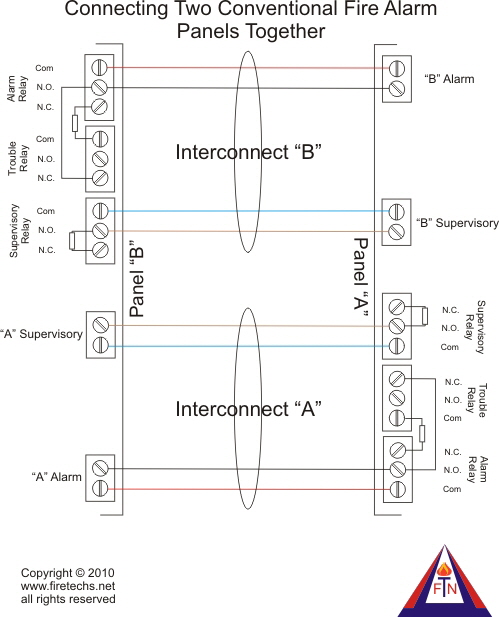
Electrical Technology Conventional Fire Alarm Wiring Https Www Electricaltechnology Org 2019 12 Fire Alarm System Wiring Html Facebook















0 Response to "42 end of line resistor wiring diagram"
Post a Comment