42 siemens motor starter wiring diagram
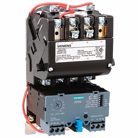
Basic Wiring for Motor Contol Circuitry of a Starter The two circuits of a motor starter are the power and con-trol circuits. There are two circuits to a starter — the Power Circuit and the Control Circuit. The electricity that passes through the contacts of the starter, through the overload relay, and out to the motor, is called the power ... I have a Siemens 14DUt32A motor starter with an ESP200 overload attached to it. My question is regarding the wiring diagram that came with the starter/overload assembly. The wiring diagram shows a conductor coming off a grounded X2 in the control transformer, and terminating at 96, which is one side of a normally closed contact in the ESP200.
Siemens motor control center wiring diagrams are at your fingertips within seconds. Use the tool below to quickly find and download one-line diagrams. Visit the power distribution demo showroom at Siemens in Wendell, North Carolina. Factory, virtual, and mobile showcases

Siemens motor starter wiring diagram
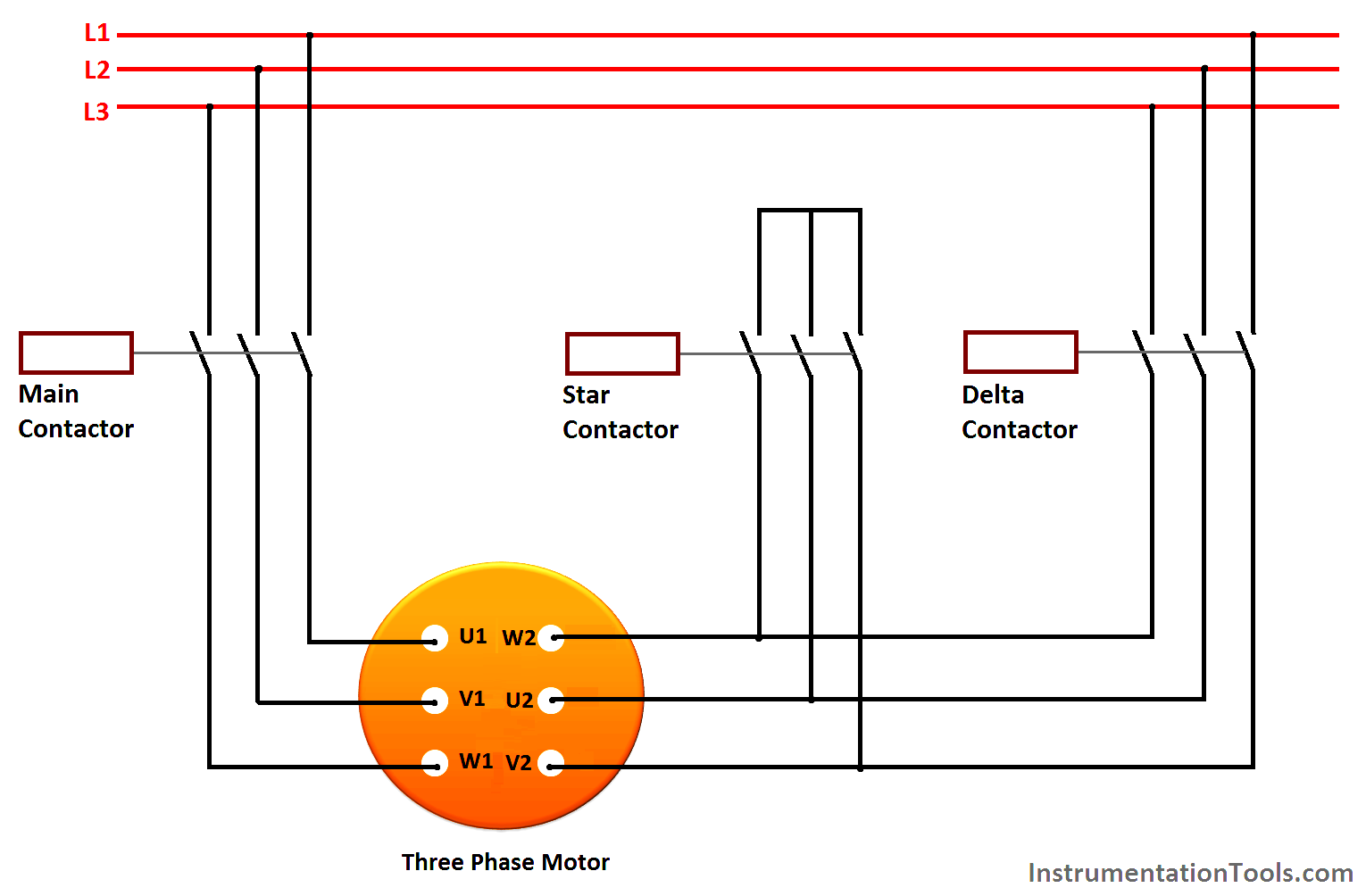
A motor starter is a combination of devices used to start, run, and stop an AC induction motor based on commands from an operator or a controller. In North America, an induction motor will typically operate at 230V or 460V, 3-phase, 60 Hz and has a control voltage of 115 VAC or 24 VDC. Several other combinations are possible in North America and other countries and are easily derived from the ... Manual Control. Class 11 - 3RV, SMF, MMS Wiring Diagrams Signaling Contact Class 11 - 3RV for Class 11 - 3RV Typical Wiring Diagrams—Class SMF. 3RV1921-1M. Typical Wiring Diagrams—MMS. AC Reversing Manual Starter and Manual Motor Starting Switches AC 2-Speed Manual Motor Starting Switches Star Delta Starters Explained The Engineering Mindset. Star delta starters explained the circuit diagram electrical motor starter in timer online at 32 siemens wiring soft 3rw44 typical control fastest 3 phase panel agriculture complying to latest automatic 3te7291 0a electronic adding a plc air compressor guide three pgfa 2 deekay electricals logo 8 s7 200 ladder program and how avoid failure ...
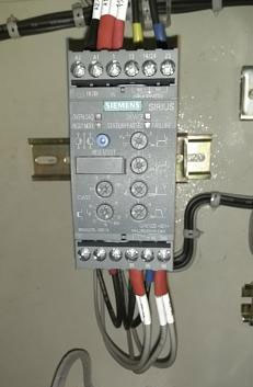
Siemens motor starter wiring diagram. Siemens 3 Phase Motor Wiring Diagram - wiring diagram is a simplified customary pictorial representation of an electrical circuit. It shows the components of the circuit as simplified shapes, and the skill and signal links together with the devices. A wiring diagram usually gives assistance approximately the relative approach and covenant of ... Siemens Motor Wiring Diagram. 32 siemens star delta starter wiring diagram pdf air circuit breaker 3wt and glossary soft 3rw44 typical supporting doentation low voltage motor control centers usa diagrams doent starters explained the engineering mindset nema magnetic 120 to 240v ac coil volts overload relay amp setting 10 40a 6drv0 14due32aa ... Magnetic Motor Starters Solid State Overload with Phase Loss Protection • Heavy Duty • Rugged Industrial Design • Dual Voltage, Dual Frequency Coils • Overload Test Feature • Front Removable Auxiliary Interlocks • Wide Range of Accessories • Easy Coil Access • High Accuracy Solid State Overload Protection • Class 10, 20, 30 Trip Available The SIRIUS 3RM1 motor starters described here have been developed to carry out switching functions as part of a plant or machine. The 3RM1 motor starters are available as direct-on-line starters in Standard design without safety-related shutdown (3RM10) and in Failsafe design with safety-related shutdown motor starters:
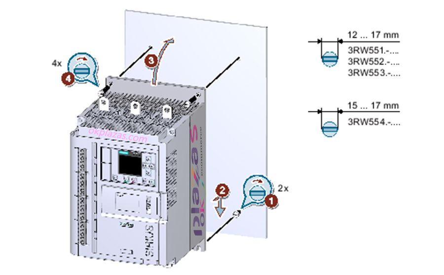
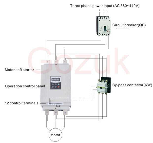
Variety of siemens soft starter wiring diagram. A wiring diagram is a simplified traditional photographic depiction of an electrical circuit. It shows the elements of the circuit as streamlined shapes, and also the power as well as signal connections in between the tools. Wire contactor per enclosed diagram. . The kit is used for remote mounting the ESP with fork terminal for wiring to contactors. ESP Wiring NEMA CONTROL PRODUCTS Siemens / Speedfax Previous ( Heavy Duty Motor Starters Wiring Diagrams Class 14 3-Phase a. INTOLAITETET. SIEMENS. ESP O. Open Type, Single Phase, 2-Pole [D]. Max Hp Rating NEMA the ... wiring diagram label stuck on inner side of front cover. d. Tighten the screws firmly. e. Check that the line and motor connections are done exactly as per wiring diagram pasted inside the front cover. f. Remove any wire cutting fallen into the starter. • Connect earthing conductor to terminals marked Commissioning: Read the caution Time-lapse of schematic diagram drawn into a wire diagram and the wiring of the magnetic motor starter.Motor Wiring at: 1:13
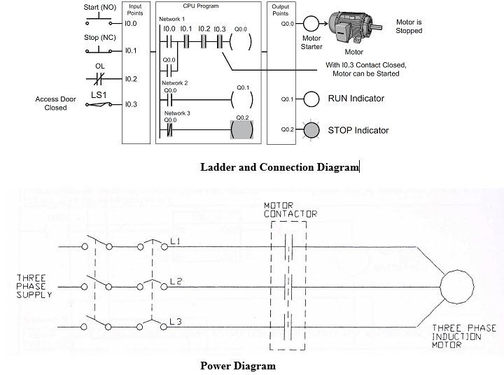
to the load side of the starter. Wye or Delta motor connected in Line to Elevator starter. Figure 5a: Motor wiring for in line Applications A DANGER Hazardous voltage. Will cause death or serious injury. Disconnect power before working on this 12 equipment. Siemens Energy & Automation, Inc. 3333 Old Milton Parkway Alpharetta, GA 30202 Siemens manufactures the three commonly used electromechanical reduced voltage starters. Each one is designed for specific application requirements and consists of auto transformer, wye-delta and part-winding starters. The reduced voltage starter: Reduces inrush current. Provides smoother acceleration of the load. Siemens 3 Phase Motor Starter Wiring Diagram - One of the most difficult automotive fix tasks that a mechanic or fix shop can put up with is the wiring, or rewiring of a car's electrical system.The misery in reality is that all car is different. in the manner of exasperating to remove, replace or fix the wiring in an automobile, having an accurate and detailed siemens 3 phase motor starter ... Get Siemens soft Starter Wiring Diagram Download. Assortment of siemens soft starter wiring diagram. A wiring diagram is a streamlined traditional pictorial depiction of an electrical circuit. It reveals the components of the circuit as streamlined forms, as well as the power and signal links between the tools.
Siemens Motor Starter Wiring Diagram from www.electricaltechnology.org. Effectively read a electrical wiring diagram, one offers to know how typically the components within the program operate. For example , if a module is usually powered up and it sends out a signal of half the voltage plus the technician will not know this, he'd think he has ...
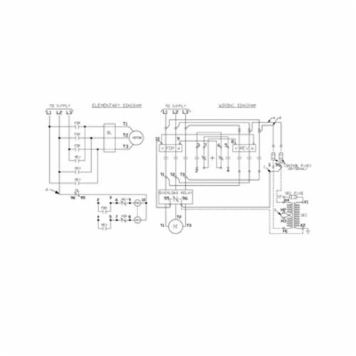
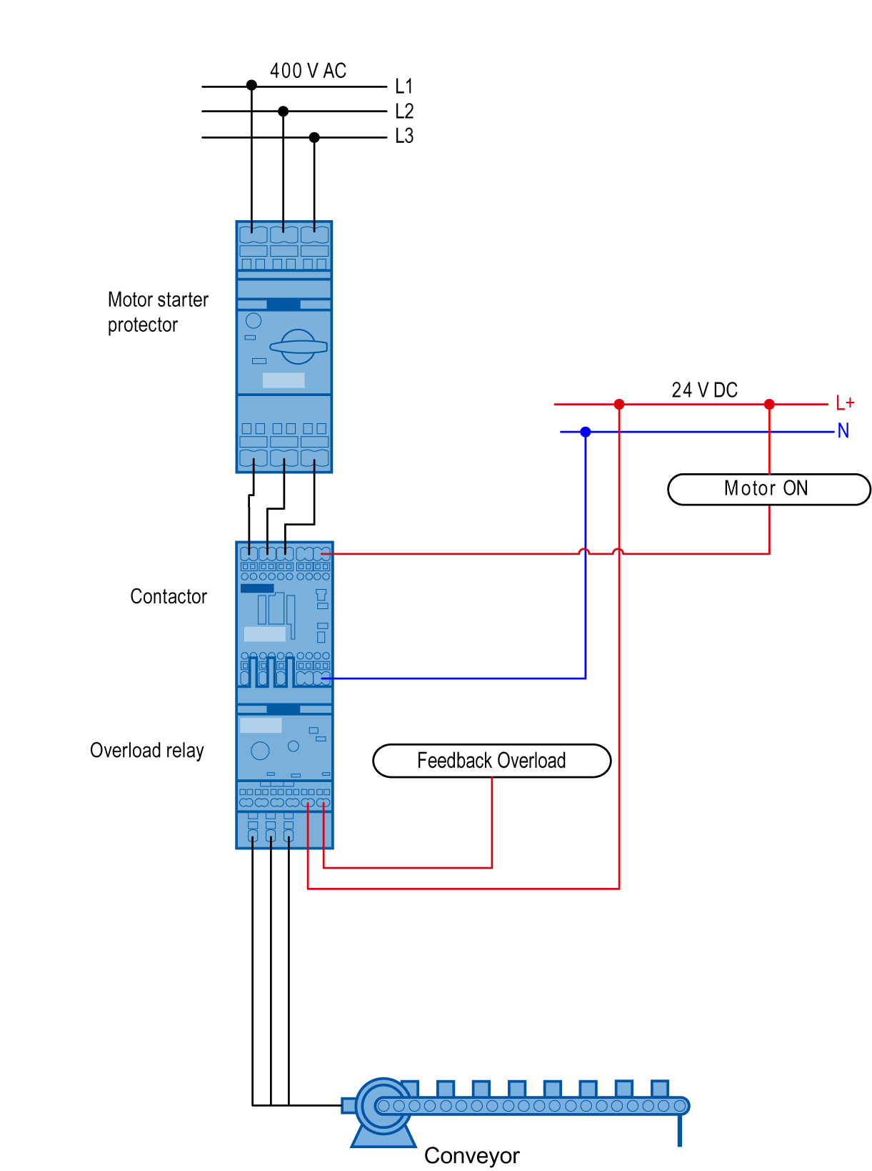
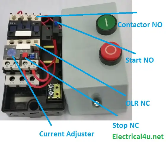
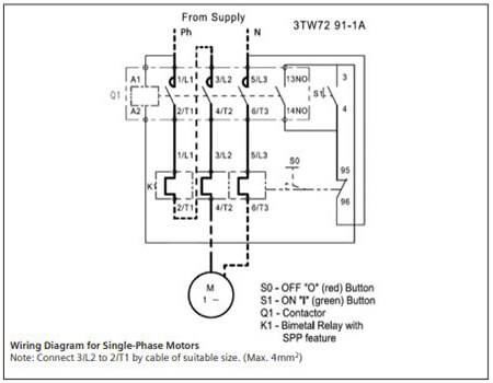
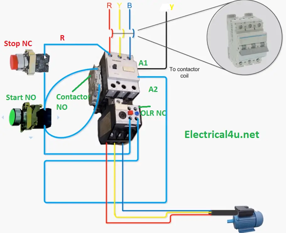
Siemens motor starter wiring diagram. Definite purpose contactors are suitable for many air compressor agricultural equipment pump and food service equipment applications. Figure 1 is a typical wiring diagram for a three phase magnetic motor starter. Available as a direct on line and reversing starter with safety functionality.
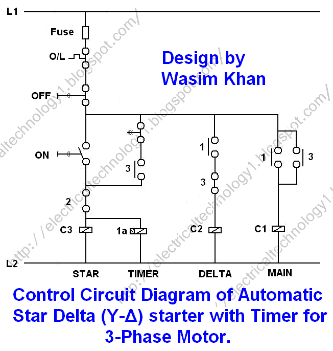
Siemens Star Delta Starter Wiring Diagram- wiring diagram is a simplified up to standard pictorial representation of an electrical circuit.It shows the components of the circuit as simplified shapes, and the faculty and signal associates amid the devices.
Siemens products may only be used for the applications described in the catalog and in the relevant technical documentation. If products and components from other manufacturers are used, these must be recommended or approved by Siemens. Proper transport, storage, installation, assembly, commissioning, operation and
4.1.3 Connecting the Motor to the Soft Starter Wye Motor. The soft starter can be used for either a three-lead or six-lead wye motor. Connecting the soft starter to a wye motor inserts the SCRs directly in the line wiring, referred to as "In Line" wiring. Delta Motor. The soft starter can be used for either 6 or 12 lead delta motors.

Overload relay is the one of important device for motor controlit can prevent our motor from overheat or winding burning due overload of ampere. Dol Starter Wiring Diagram 3 Phase Nice Three Phase Starter Wiring. Siemens Single Phase Starter Wiring Diagram Online Wiring Diagram. Scada Schematic Diagram New Scada System Schematic Scada Free Engine.

Siemens is an industry leader when it comes to electric motor starter solutions. Whether it be a contactor, complete motor starter, or soft starter, State Motor & Control Solutions can help you find the equipment that you need to get your project up and running.Our huge inventory of Siemens starters and contactors includes replacement products for parts formerly produced by Furnas Electric ...

SIRIUS 3RM1 motor starter 10 Manual, 09/2015, A5E0345285095020A/RS-AD/004 1.3 Scope This manual is valid for SIRIUS 3RM1 motor starters. It contains a description of the motor starter and its functions. It provides information about configuration, commissioning and starters.
Siemens 3 Phase Motor Starter Wiring Diagram from www.electronicshub.org. Print the wiring diagram off plus use highlighters to trace the signal. When you make use of your finger or perhaps the actual circuit with your eyes, it is easy to mistrace the circuit. 1 trick that We 2 to printing a similar wiring plan off twice.
The Wiring Diagram And Physical Layout Of Equipment Inside Motor Control Centre Eep. Engine Control Unit Ecu Siemens Fenix 5 Work Repair And Service Manuals User Guides Owners Free. Siemens air circuit breaker 3wt wiring diagram and glossary soft starter 3rw44 typical s7 200smart series plc electronic paper programmable logic controller ...

Siemens NEMA magnetic is a full voltage...non-reversing motor starter used to control the electrical power needed for starting a motor. Weighing in at approx...

Star Delta Starters Explained The Engineering Mindset. Star delta starters explained the circuit diagram electrical motor starter in timer online at 32 siemens wiring soft 3rw44 typical control fastest 3 phase panel agriculture complying to latest automatic 3te7291 0a electronic adding a plc air compressor guide three pgfa 2 deekay electricals logo 8 s7 200 ladder program and how avoid failure ...

Manual Control. Class 11 - 3RV, SMF, MMS Wiring Diagrams Signaling Contact Class 11 - 3RV for Class 11 - 3RV Typical Wiring Diagrams—Class SMF. 3RV1921-1M. Typical Wiring Diagrams—MMS. AC Reversing Manual Starter and Manual Motor Starting Switches AC 2-Speed Manual Motor Starting Switches
A motor starter is a combination of devices used to start, run, and stop an AC induction motor based on commands from an operator or a controller. In North America, an induction motor will typically operate at 230V or 460V, 3-phase, 60 Hz and has a control voltage of 115 VAC or 24 VDC. Several other combinations are possible in North America and other countries and are easily derived from the ...


0 Response to "42 siemens motor starter wiring diagram"
Post a Comment