40 submersible pump wiring diagram
Jun 28, 2017 - A guide of 3 phase submersible pump wiring diagram with direct online starter using contactor , mccb, overload relay and push button switches. Today I am here to share with you the 3 phase submersible pump wiring diagram .
Hi all, sorry for the panic. I have rewired my septic tank submersible pump and air blower so that I can incorporate a digital timer switch. It's a Müller SC 28.21 pro4 timer like this: https://charter-controls.com/products/sc28-21pro4-230vac/ However, I have wired the L and N input but I can't seem to get any power output to the air blower or pump, despite the timer being set as "on". So the question I have is how am I supped to wire this digital timer switch? I assumed it was L+N in and the...
Submersible Pump Wiring Diagram from static-assets.imageservice.cloud. Effectively read a cabling diagram, one provides to learn how the components inside the program operate. For instance , if a module is powered up also it sends out a new signal of half the voltage plus the technician will not...

Submersible pump wiring diagram
Today I am here to share with you the 3 phase submersible pump wiring diagram. In which I control a three phase submersible pump motor using magnetic contactor. Not only a contactor but also I install the thermal overload relay which will protect the motor form burning in case of over current flow to the...
submersible pump wiring diagram - What's Wiring Diagram? A wiring diagram is a type of schematic which uses abstract pictorial symbols to show each of the interconnections of components in a very system. Wiring diagrams are made up of certain things: symbols that represent the...
2 wire submersible well pump wiring diagram a newbie s overview of circuit diagrams. Single phase submersible motor starter wiring diagram explanation. Pump control panel wiring diagram schematic just whats wiring diagram. May 22 2018 by headcontrolsystem.
Submersible pump wiring diagram.
Fully submerged submersible pump sets like electric cables are exempt from ATEX Ex Marking. Submersible-motor pumps are subjected to a thorough inspection before leaving the factory and are 3.5.1 Stator winding The stator winding consists of winding wire provided with special insulation.
2 wire submersible well pump wiring diagram a newbie s overview of circuit diagrams. This video shows wiring a franklin submersible pump control box. You can also find other images like wiring diagram parts diagram replacement parts electrical diagram repair manuals engine diagram engine...
Name: submersible pump wiring diagram - Submersible Well Pump Wiring Diagram Fresh Fine Simplex Pump Wiring Diagrams Electrical Collection of submersible pump wiring diagram. Click on the image to enlarge, and then save it to your computer by right clicking on the image.
A typical submersible pump works in a reasonably simple way. It starts by converting rotary energy into kinetic energy by using pressure energy pulled in...
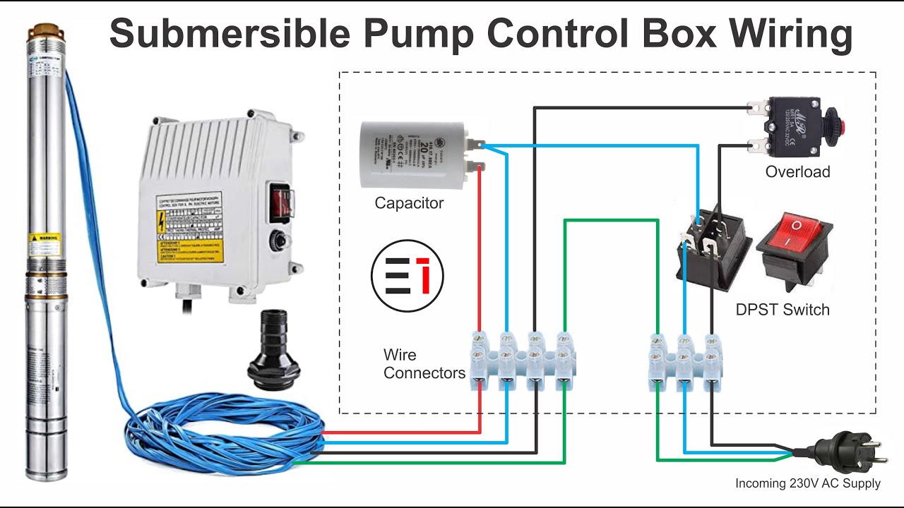
1 Phase Three Wire Submersible Pump Starter Wiring Diagram. In this single phase submersible pump control box diagram I shown the incoming AC supply L and N. A DPST (double pole single through switch), reset able thermal overload protector and motor starting capacitor with all connection.
First, see the 3 phase submersible pump wiring diagram and after that, I will explain each step of the below connection diagram. You can ask your question according to the three phase submersible pump wiring diagram in the below comment section. One thing more the above diagram and text in...
Submersible Pump Wiring Diagram Source: qph.fs.quoracdn.net. Read wiring diagrams from bad to positive in addition to redraw the circuit being a straight line. All circuits are usually the same - voltage, ground, single component, and buttons.
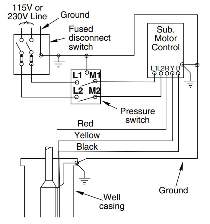
3 Wire Submersible Pump Wiring Diagram. Beauchamp Water Treatment Blogspot Submersible Well Diagrams.
collection of 3 wire submersible pump wiring diagram wiring diagram panel pompa submersible a submersible pump can be either two or three wire regardless of the voltage coming from the panel so trigger get going at your pump and follow the conduit back.
A wiring diagram is typically utilized to repair issues and also to earn sure that all the connections have been made and also that whatever exists. submersible well pump wiring diagram.
Grinder Wiring Diagram Data Wiring Diagram. Pond Water Garden Installlation Maintenance Guide. This troubleshooting information is intended to guide in the general determination of pump problems and their solutions. Wiring diagram for submersible pump. Fulfillment by amazon fba is a service...
I recently installed a buck-boost transformer in one of our commercial buildings, here in Harris County, Texas, with 208Y/120v service to support a 1hp submersible well pump rated for 230v, single-phase. The transformer is a [GE 9T51B0158](https://www.geempower.com/ecatalog/ec/EN_NA/p/9T51B0158) which is labeled for 208v primary x 240v secondary, up to 500va. Per the label diagram, I connected 208v nom. (210v measured at the transformer) to X1 & X2, tied H2 to H3, and then took a meter rea...
Wiring diagram for 220 volt submersible pump, http ...
**Introduction** This is a 60% distilled water and 30% ethylene glycol chiller using an 8000 BTU r410a window AC. Current sustained liquid temperatures are around -2/-3c with the PC at idle, sustained load has it crawl up to 1c after 30 minutes of a 250w CPU heat load. The temperature sensor is set to have the AC turn on when temperatures fall below -2c. A TMP36 in plastic bags with tape is inserted into the liquid in the reservoir to measure temperature, once below -2c is detected an LED light...

Submersible water pump starter wiring connection diagram
Well pump wiring diagnosis & repair: this article describes troubleshooting a submersible well pump that was causing tripped circuit breakers and that pumped water only at a slow, reduced rate and pressure. Best ebook you must read is Franklin Electric Submersible Pump Wiring Diagram.

Single phase control panel wiring diagram | submersible pump ...
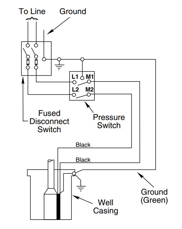
Service Manual. Submersible pumps • jet pumps. Typical wiring diagrams. 2-Wire Pump Wiring Diagram with PumpSaver Plus 233P. 32.

Water pump motor wiring diagram - electrical blog
Single Phase Submersible Pump Starter Wiring Diagram 3 Wire Well - 3 Wire Submersible Pump Wiring Diagram. There are just two things that will be found in any 3 Wire Submersible Pump Wiring Diagram. The first element is symbol that indicate electrical element from the circuit.
How to install and wire a well pump - well pump installation guide
The pump size, tank size and other controls should be selected to keep the starts per day as low as practical for longest life. Franklin submersible motors are designed primarily for operation in the vertical, shaft-up position. Three-Phase Starter Diagrams.

Submersible pump microcontroller wiring diagram three-phase ...
Submersible pump wiring diagram. Not only a contactor but also i install the thermal overload relay which will protect the motor form burning in case of over A wiring diagram is a streamlined traditional photographic representation of an electrical circuit. 2 wire submersible well pump wiring diagram a...
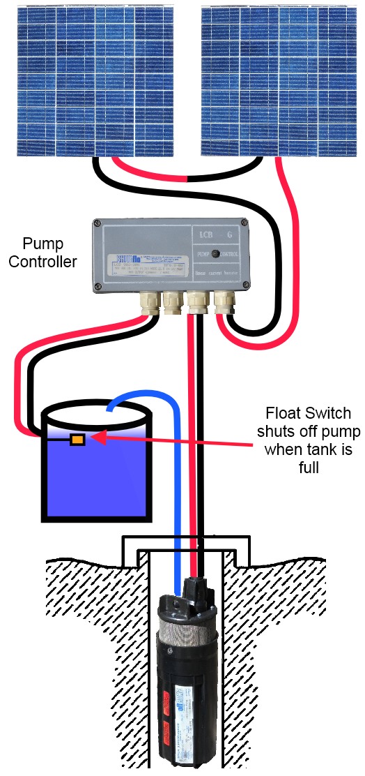
How to use a submersible water pump - 24 volt wiring diagram
Today I made Automatic Hand Sanitizer WITHOUT ARDUINO, if you want to make it, prepare the following items 1. Empty Bottle 2. Plastic bottle ( small) 3. Submersible-Water-Pump DC 4. IR Sensor 5. TIP32C-Transistor 6. LED 7. Rocker Switch 8. 1kohm Resistors (2) 9. Wires 10. Glue gun 11. Soldering Iron Follow the pin diagram to solder and attach switch and LED thru the negative wire from battery to Vcc ( IR sensor) Follow the step by step in the video as shown You will be able to complete and e...

Wiring diagram for 220 volt submersible pump, http ...
3 Phase Pump Wiring Diagram. Use your socket wrench and unscrew the 2 bolts that keep the starter in place. The starter is connected to the fly-wheel and similar to you pull the screws out it should come right out. on purpose set the starter next to on a towel and unscrew the black wire.
How to install and wire a well pump - well pump installation guide
A wiring diagram is often used to troubleshoot problems and to create definite that every the links have been made and that whatever is present. troubleshooting residential submersible pump systems practical. Architectural wiring diagrams pretend the approximate locations and interconnections of...
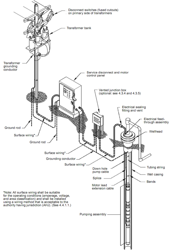
Submersible pump system overview: main surface and downhole components
Single Phase Submersible Pump Starter Wiring Diagram On Water Control Panel Inside To Submersible Pump Submersible Well Pump Sump Pump. Float Switch Connection Auto Manual Single Phase Water Pump Youtube Electrical Circuit Diagram Electrical Projects Water Pumps.

Detail dump trailer wiring diagram submersible pump well pump ...
Wiring Diagram For Pressure Switch New Funky Franklin Submersible. Well Pump Control Box Wiring Diagram Inspirational - Wiring Diagram. Building circuitry layouts show the approximate locations and interconnections of receptacles, lighting, and also permanent electric services in a...

Automatic water level controller wiring diagram for 3 phase motor ...
4" and 6" SUBMERSIBLE PUMPS. Submersible Well Pump water pump pdf manual download. Code, and local codes for all wiring. Follow wiring instructions in this manual when

Wiring diagram panel pompa submersible 3 phase
Submersible pumps are multi-stage centrifugal pumps that are designed as their submersible electric motors work under the water. Motor bearings are lubricated with the water that is filled inside the submersible electric motor and cooling operation for the bearings is provided by the water in the well...

Submersible well pump wiring diagrams | lovetoknow
Multistage monobloc submersible pump with hydraulic section below the motor, which is cooled by the pumped liquid. Impellers and diffusers made of fibreglass Stator enclosed in airtight casing made of AISI 304 stainless steel and covered by an outer protection that protects the wiring and the capacitor.

Single phase 3 wire submersible pump wiring diagram
Electric submersible pumping (ESP) utilizes a submerged electrical motor driving a multistage centrifugal pump. Reduction of the high workover costs can be accomplished if the ESP unit is run on a wire rope of It plots as a straight line on a pressure vs liquid flow rate diagram, as shown in Fig.

Aim manual - page 54 | single-phase motors and controls | motor ...
Two diagrams showing how to use a submersible water pump that runs on 24 volt solar panels or batteries. Pump runs when pressure drops in the pressure tank. Both setups use two 12 volt, 60 or 90 watt solar modules "wired in series" to make 24 volts.

Single phase submersible pump starter wiring diagram gooddy org ...

Automatic water level controller circuit diagram for submersible pump

3 phase submersible pump wiring diagram with dol stater

Water pump wiring troubleshooting & repair pump wiring diagrams

Wiring diagram pompa air
How to wire submersible motor control box | by "elektricar 1"

Electrical education - 3 phase submersible pump wiring diagram ...
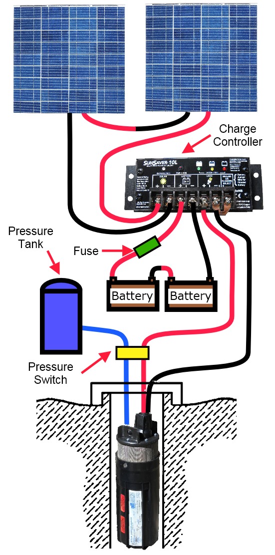
How to use a submersible water pump - 24 volt wiring diagram

Detail 44 luxury single phase submersible pump starter wiring ...

Typical electrical submersible pump system and main components ...

Detail submersible motor control box wiring single phase water ...
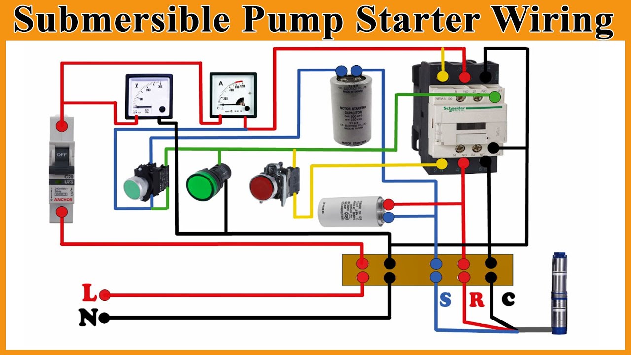
Submersible starter connection with magnetic contactor | submersible water pump starter wiring |

Circuit diagram of water pump control system | download scientific ...

Real power engineering - submersible pump control box wiring ...
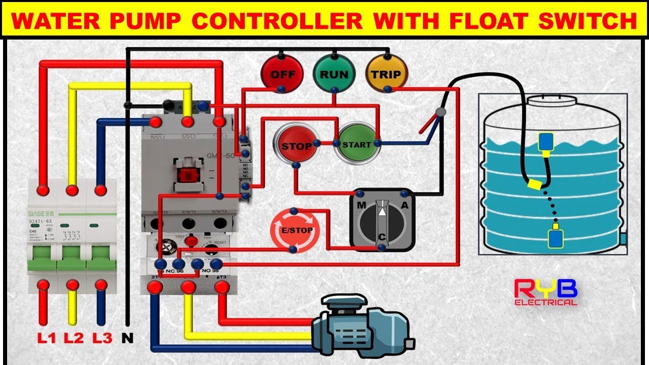
3 phase dol starter control and power wiring diagram! water pump controller with float switch

Submersible water pump control panel wiring diagram | electrical technologies

Submersible well pump wiring diagrams | lovetoknow

Phase sequence wiring diagram c-liquid level relay (l.l) is used ...

Electric pump auto-manual wiring diagrams (3-phase motors) - my ...

Wiring diagram for automatic water pump using floatless level ...

Detail wiring diagram for 220 volt submersible pump http ...
Pompa submersible, pompa, diagram pengkabelan gambar png

Submersible pump control wiring diagram - submersible pump box control wiring diagram -control wire
0 Response to "40 submersible pump wiring diagram"
Post a Comment