42 livewell timer module wiring diagram
The Subaru EJ204 was a 2.0-litre horizontally-opposed (or 'boxer') four-cylinder petrol engine with double overhead camshafts. The naturally aspirated E204 engine was initially introduced in the 2005 Subaru GD/GG Impreza and 2006 Subaru BL/BP Liberty as a more powerful alternative to the single overhead cam EJ202 engine, but effectively replaced the EJ202 when the GE/GH Impreza was released in ... Livewell timer using Rig Rite #520 timer module
100% money-back guarantee. With our money back guarantee, our customers have the right to request and get a refund at any stage of their order in case something goes wrong.
Livewell timer module wiring diagram
Wiring Diagram January 03, 2020. Livewell Timer Module Wiring Diagram Stage Pin Wiring Diagram Wiring Diagram is one of the pictures that are related to the picture before in the collection gallery, uploaded by autocardesign.org. You can also look for some pictures that related to Wiring Diagram by scroll down to collection on below this picture. Communities in Manitoba. Community Documents Find community resource documents to facilitate municipal administration, public works, recreation and wellness, environmental services, protective services, community development, land-use planning, community planning, and … data:image/png;base64,iVBORw0KGgoAAAANSUhEUgAAAKAAAAB4CAYAAAB1ovlvAAACs0lEQVR4Xu3XMWoqUQCG0RtN7wJck7VgEW1cR3aUTbgb7UUFmYfpUiTFK/xAzlQWAz/z3cMMvk3TNA2XAlGBNwCj8ma ...
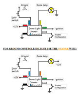
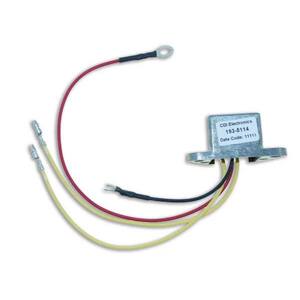
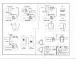
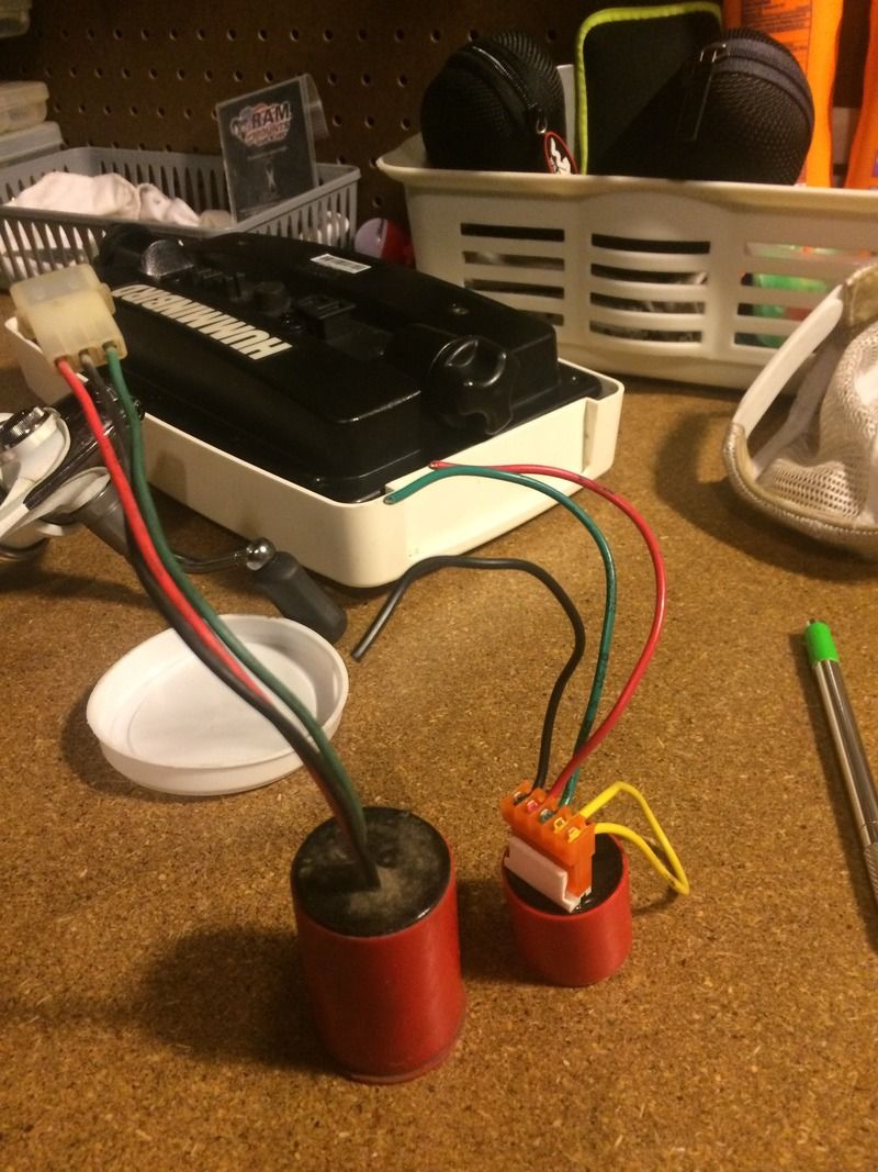
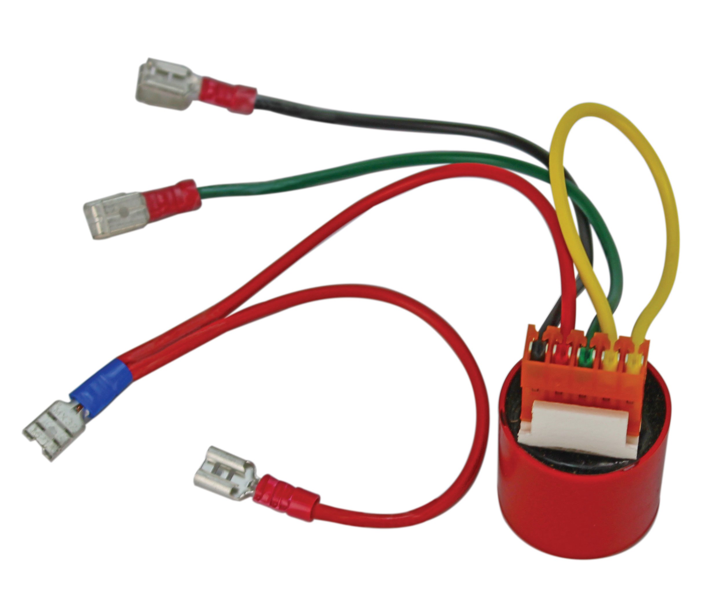
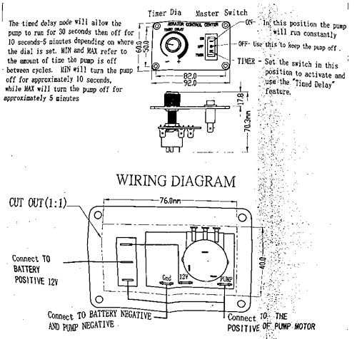
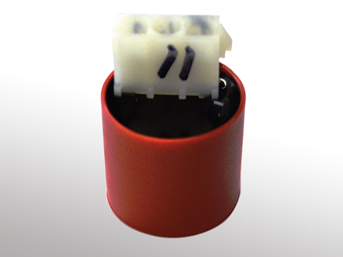
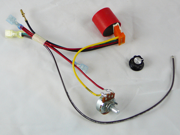
Livewell timer module wiring diagram. Sep 30, 2021 · N. Korea's parliamentary session. This photo, released by North Korea's official Korean Central News Agency on Sept. 30, 2021, shows Kim Yo-jong, North Korean leader Kim Jong-un's sister and currently vice department director of the ruling Workers' Party's Central Committee, who was elected as a member of the State Affairs Commission, the country's highest decision-making body, during the ... Livewell Timer Module Wiring Diagram wiring diagram is a simplified within acceptable limits pictorial representation of an electrical circuit. A wiring diagram usually gives guidance roughly the relative face and. 20 see pages 14 and 15 industrial duty door operator for other wiring configurations patent pending the maintenance alert system ... 6002 LIVEWELL CONTROL CENTER HOOK UP DIAGRAM Installation Select a location for mounting the Control Panel, cut a hole 1-7/8” x 1-5/8” (see sheet 2), secure panel with #8 sheet metal screws. After mounting panel, string wire to battery and pump areas. The RED wire connects to the Battery (+) positive, the BLACK wire connects to the Pump (-) LIVEWELL TIMER INSTALLATION INSTRUCTIONS. INSTALLATION TOOLS. PUMPS. LEAVE THE PLASTIC CONNECTOR COVER IN PLACE ( black square in middle of timer ) To connect your adjustable livewell timer into your current boat you will need to buy some 16 gauge wire, I recommend buying 3 different colors. One for power (red), one for ground (black), and one for the pump (brown).
Mar 3, 2012. #2. Re: Wiring Diagram for livewell pumps and bilge pump. Here is your bilge pump wiring. You'll notice two brown wires. The hot wire goes directly from the battery to the switch and then pigtails into the pump. The other brown wire goes to the float switch. This allows the bilge pump to run when the 3-way switch is put into manual ... You need to verify the current wiring of your livewell switch, its power connection, and whether you have a separate dial that would change the delay time of your livewell. Then, knowing the color of the wires going to power, ground, switch, pump and possibly the timer resistor wire accordingly - to the instructions listed at the top of the page. Take A Sneak Peak At The Movies Coming Out This Week (8/12) New Movie Releases This Weekend: December 1-5; New Movie Trailers We’re Excited About Symposia. ITMAT symposia enlist outstanding speakers from the US and abroad to address topics of direct relevance to translational science. Read more
ALL YOUR PAPER NEEDS COVERED 24/7. No matter what kind of academic paper you need, it is simple and affordable to place your order with Achiever Essays. Livewell Timer Module Wiring Diagram Livewell Wiring Diagram Wiring Diagram is one of the pictures that are related to the picture before in the collection gallery, uploaded by autocardesign.org.You can also look for some pictures that related to Wiring Diagram by scroll down to collection on below this picture. If you want to find the other picture or article about Livewell Timer Module ... We would like to show you a description here but the site won’t allow us. Solid-state cycle module switches pump to on, or to a run time of 30 seconds on/. An easy-to-follow wiring diagram and easy-set design makes this a perfect timer for both residential and commercial applications. This to voltage, amp timer is rated at 5-hp maximum at volts, and has a maximum of 12 cycles. It also includes the Omron Repeat Cycle ...
Bass boat livewell diagram [email protected] Manual - Pump stays on 5 - Pump will run for 1min and off for 5 min 960 W. 15' Bass Boat - bass fishing boat. Aluminum fishing boats combining quality, fishability and affordability in a large offering of outboard mod-v bass boats, deep v boats, and jon boats. These bass boats have all the features ...
Automatic Livewell Timer. PART #500. Automatically turns livewell pump on and off! Cycle position turns pump on for 30 seconds every 3 minutes; Keeps bait or fish alive without draining battery down; Easily replaces your on-off switch; 3/8” mounting hole for dashes up to 1” thick. Skin Carded. View #500 Switch wiring diagram

data:image/png;base64,iVBORw0KGgoAAAANSUhEUgAAAKAAAAB4CAYAAAB1ovlvAAACs0lEQVR4Xu3XMWoqUQCG0RtN7wJck7VgEW1cR3aUTbgb7UUFmYfpUiTFK/xAzlQWAz/z3cMMvk3TNA2XAlGBNwCj8ma ...
Communities in Manitoba. Community Documents Find community resource documents to facilitate municipal administration, public works, recreation and wellness, environmental services, protective services, community development, land-use planning, community planning, and …
Wiring Diagram January 03, 2020. Livewell Timer Module Wiring Diagram Stage Pin Wiring Diagram Wiring Diagram is one of the pictures that are related to the picture before in the collection gallery, uploaded by autocardesign.org. You can also look for some pictures that related to Wiring Diagram by scroll down to collection on below this picture.


0 Response to "42 livewell timer module wiring diagram"
Post a Comment