37 egr valve wiring diagram
(1983 Ford Ranger 2.8L V6 Engine Vacuum Diagram) (1984 Ford Ranger 2.3-Liter 4-Cylinder Vacuum Line Diagram) Vacuum Diagram Definitions Abbreviation Description A/CL Located in the air cleaner A/CL DV Air Cleaner Diverter Valve A/CL BI MET Air Cleaner Bi-Metallic Valve A/CL CWM Air Cleaner Cold Weat... 19. Valve Cover 26. Exhaust Gas Recirculation (EGR) Cooler 20. Intake Air Heater (IAH) 27. Oil Pan 21. Thermostat 28. Starter Motor 22. Belt Tensioner 29. Turbocharger 23. Coolant Pump 30. Exhaust Gas Recirculation (EGR) Valve 24. Coolant Filter Mack Body Builder Instructions CHU, CXU, GU, TD, MRU, LR
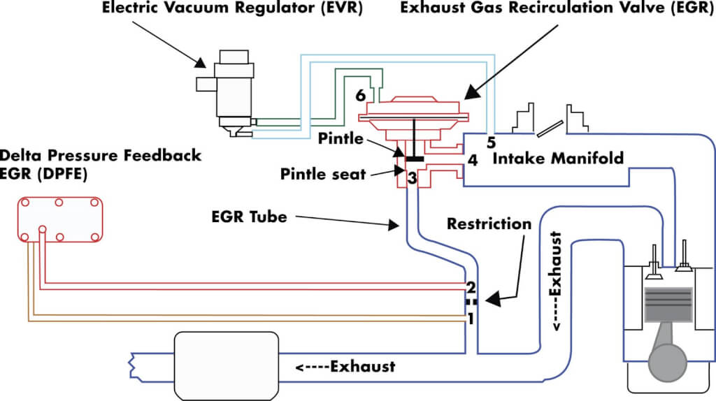
The EGR vacuum diagram for your particular vehicle is displayed on the Vehicle Emission Control Information (VECI) label. The EGR system is Differential Pressure Feedback EGR (DPFE) system, controlled by the Powertrain Control Module (PCM) and composed of the following components: DPFE sensor (also referred to as the back pressure transducer ...

Egr valve wiring diagram
Vehicle wiring harness EGR valve emulator MAF Cut Pin 5 Pin 1 - not used Vehicle wiring harness [!] NOTE Installation completed. Normal emulator operation, EGR valve should be closed Check EGR valve, if not closed, close it. Installation in Mercedes Benz Emulator EML810/23 electrically compatible with MB cars that use a "Wahler" EGR valves ... Re: wiring diagrm for egr valve 2009 jeep wrangler 3.8. JK jeep, i have 08 and full docs. it wires to the PCM, same wire colors. as you can see drawing dont work right in fixya. they get "crunched" badly". the EGR is PWM modulated, first is to clean in. the exhaust path must be good. the EGR must not stick closed or open. EGR system 6.7L Ram wiring diagram. P241a code. same year, model, engine as thread. Replaced. P241a code. same year, model, engine as thread. Replaced both o2 sensors, … read more. I have a 2013 2500 6.7 it has a p2bac and a p003a.
Egr valve wiring diagram. Connect a hand vacuum pump to the EGR valve in place of the vacuum hose and apply 15 in-Hg of vacuum to the valve (if you don't have access to a vacuum pump you may borrow-rent one from a local auto parts store). As you apply vacuum to the valve, check for diaphragm movement. Also, pay attention to engine idle. Egr Valve Wiring Diagram. Multiple fault codes may log due to open and short circuits in. The wiring diagram is an easy visual representation of the physical connections and physical layout of your electrical system or even circuit. It might free off and work for a bit or work for longer if whatever is making it stick can be cleaned. Note there is not a line item EGR Valve. The 1st is a wiring diagram dash to sensors, or sensors to dash lights. However you want to look at it. Unless you can point out the actual location of the VPODS to ECM. Ddec 5 Ecm Wiring Diagram (Nov 24, ) ― This best photo collections about ddec 5 ecm wiring diagram is available to save. ... Mar 06, 2017 · Location and descriptions of the fuses and relays of the under-hood fuse box for 1997-1998 Ford F150, F250 and Expedition. The under-hood fuse/relay box is known as the Power Distribution Center in the Ford service/repair literature.
The signals generated from the EGR valve are 5 volt digital signals that reflect one of three positions of the rotor of the brushless DC motor. These are typically called hall effect outputs. The transitions on channel B occur about 1/3 of the pulse width after the transition of channel A. Channel C transitions happens about 2/3 of the way ... The EGR system module (ESM) is one of Ford's latest EGR system for gasoline engines. It is an EGR valve, EVR, MAP and DPFE sensor rolled into one package. Though the DPFE sensor on an ESM is referred to as "DPFE" by the scan tool and also wiring diagrams, it is not a traditional DPFE sensor as used on the older EGR system. It is actually two separate MAP sensors. I've determined that the valve has two 21 ohm coils. I expose these coils (together, or separately) to 12VDC but the valve does not open. I can feel the solenoid twitching slightly in response to applied voltage, but it is a long way from opening up. Before I reassembled the EGR valve I verified that its polished push rod moved freely. VW Transporter EGR valve pin data. erwin. Kev. A 5 pin EGR is quite likely the same as other (not all) 5 pin EGR's. Guess at it ! Pin configurations will be different but I guess you will have 3 pins for position feedback, and pwm power supply on the other 2.
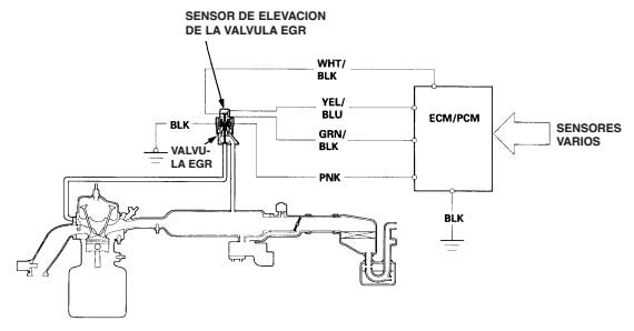
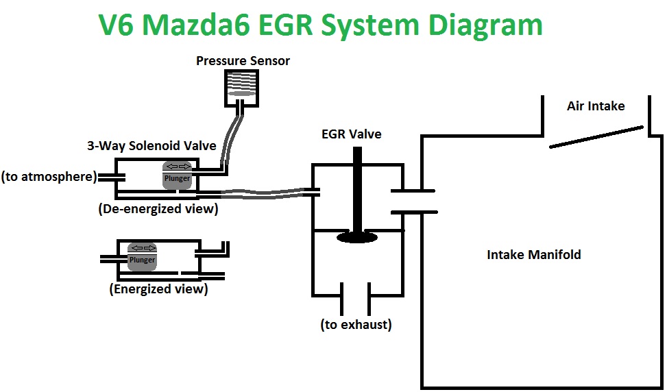
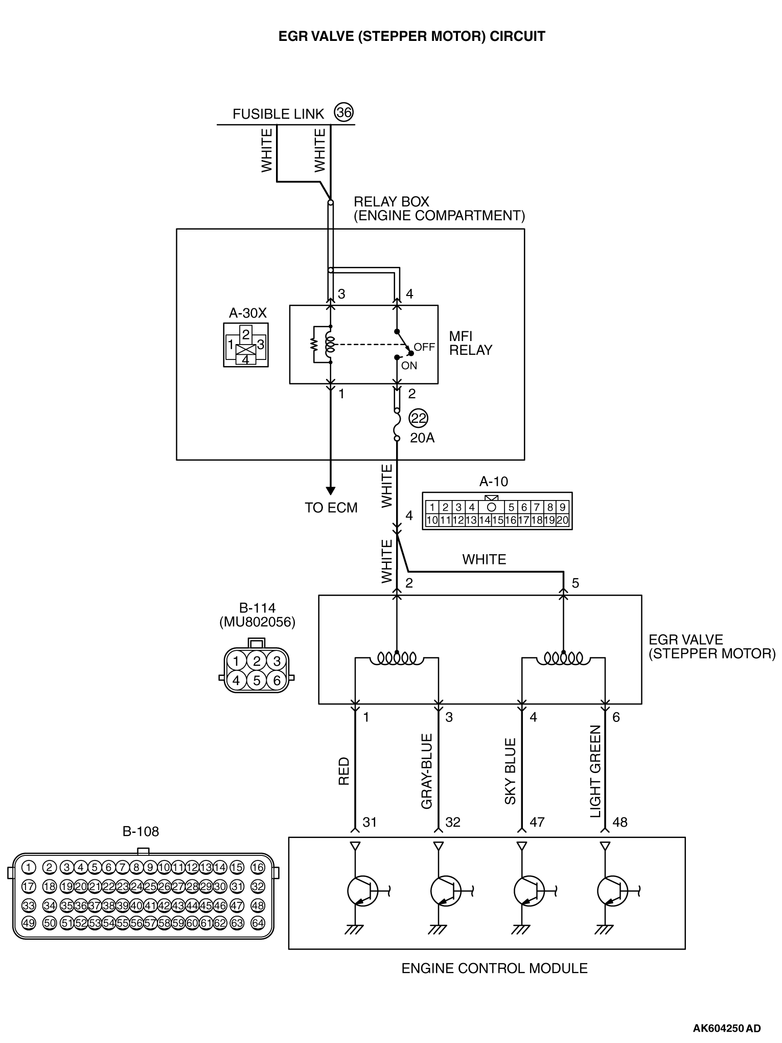
The EGR valve is normally closed. There is no EGR flow when the engine is cold, at idle, or during hard acceleration. The EGR flow is at its peak during steady cruising under moderate load. In some cars, the EGR valve is operated by a vacuum actuator, as in the first diagram below. Modern cars have an electric EGR valve with a step motor. EXHAUST GAS RECIRCULATION (EGR) COOLER — EXPLODED VIEW, 6.7L DIESEL EGR valve cooler (View 1 of 3) Click to Enlarge Item Part Number Description 1 8075 EGR valve coolant vent hose 2 9Y438 Coolant hose retainer ... 14 — Wiring harness retainer (part of 12B637) 15 — Wiring harness retainer (part of 12B637) ... wiring diagram index name description page aa power distribution frc 3 ab power distribution frc 4 ac power supply, circuit protection 3/4 (ef 5 ad power supply, circuit protection 4/4 (ef 6 ae grounding 7 The signal voltage is always 12[volt] when EGR valve is not operated. If it is ON/OFF ... Check the EGR type (On/Off, Duty, EEGR) through wiring diagram.15 pages
Mazda 6 Service Manual - Egr valve inspection - Emission ...
If the EGR valve refuses to open it would be time to check the wiring harness for voltage at the plug that goes into the EGR. If the voltage is OK, then replacing the EGR valve may be a good idea. There's plenty on testing this wiring in the next section. Carbon, junk, and even ice can cause the EGR circuit to stick. The most common cause of ...

Egr Solenoid Wiring Diagram - Tuts Crank
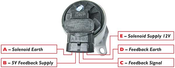
The EGR Tester is simply connected either via a dedicated connector for the particular valve - if available - or with universal push-on terminals sized to suit the pins in the valve connector. If the valve has a position sensor, the connector will have multiple pins - often five or six - so care needs to be taken to connect to the correct pins.

2005 Equinox Egr Valve Wiring Diagram - puertoricoinform
1244: EGR proportional solenoid valve. 1245: altitude switch. 1246: EGR function supply relay. 1247: EGR coolant thermal switch. 1248: EGR calibration resistor. 1249: load lever potentiometer (EGR). 1250: EGR exhaust gas recycling control unit. 1251: EGR vacuum pump. 1252: diesel advance corrector relay. 1253: all or nothing solenoid valve (EGR).
1996-1998 EGR Valve Lift Sensor Circuit Diagram (1.6L Civic)
WIRING DIAGRAM COMPONENT LOCATIONS. When trying to locate a component in a wiring diagram and you don't know the specific system where it is located, use this handy component locator to find the system wiring diagram in which the component is located. Then, go to that system and locate the component within the wiring diagram.
Exhaust Gas Recirculation Valves (EGR)
In this video I show another variable when it comes to testing this type of EGR valve. (open 5v reference circuit from a bad engine computer) I'll also show ...
2004 mazda rx8 fuel injector connector diagram - RX8Club.com
Service had been done previously that was my first port of call. Live data says that the air and fuel are OK. Done an actuator test on the turbo, tuobo position sensor says it is ok, done a command test on the EGR valve it is opening and closing, stripped the wiring from the EGR to the ECU all 4 wires are OK.

Egr Valve Wiring Diagram
Dec 07, 2021 · LRS-9428A-EGR POSITION SENSOR: Many times the pesky check engine light is the cause of a faulty EGR Valve Position Sensor. This sensor allows the Powertrain Control Module to keep tabs on the EGR valve to make sure it opens and closes at all of the proper times. If the PCM reads something out of the ordinary it will illuminate the check engine ...

21 Lovely Egr Valve Wiring Diagram
Replaced siemens egr valve with retrofit delphi egr valve need to rewire connector have wiring diagram for new connector need to know how to change to new connector there are two grey wires Whats the difference in egr tubes in a chevy equinox if it has been retrofitted or has the original.Chevy Equinox Wire Diagram: Electrical Problem Chevy EGR ...

Good egr voltages - Maintenance / Servicing / MOT ...
Fuse box diagram (location and assignment of electrical fuses) for Volvo S40 (2004, 2005, 2006, 2007, 2008, 2009, 2010, 2011, 2012).

| Repair Guides | Gasoline Engine Emission Controls ...
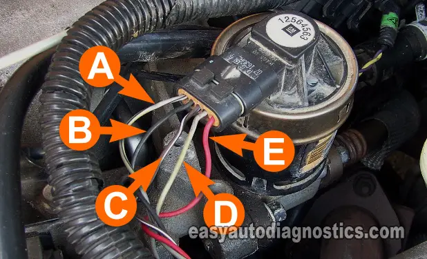
Step 3. Turn the multimeter on and set the dial to "Volts DC." Attach the red lead wire to the EGR circuit labeled "C." There are five circuits on the EGR and each is labeled A-E. Connect the black multimeter lead to a ground point, such as the battery negative cable. Turn the ignition key to the "On" position.

Diagram and details of an egr problem for a 2001 chevy ...
Diagrams are arranged such that the power (B+) side of the circuit is placed near the top of the page, and the ground (B-) side of the circuit is placed near the bottom of the page. All switches, components, and modules are shown in the at rest position with the doors closed and the key removed from the ignition. Components are shown two ways.
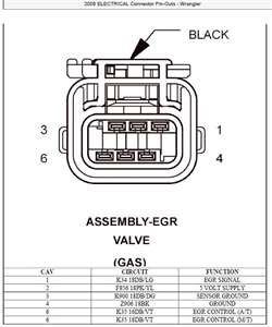
SOLVED: Wiring diagrm for egr valve 2009 jeep wrangler 3.8 ...
In this article, we consider the fourth-generation Chevrolet Corvette (C4), produced from 1990 to 1996. Here you will find fuse box diagrams of Chevrolet Corvette 1993, 1994, 1995 and 1996, get information about the location of the fuse panels inside the car, and learn about the assignment of each fuse (fuse layout) and relay.

Duramax Sel Parts Diagram - Wiring Forums
EGR valves either become stuck in the open position or stuck in the closed position, so once you've figured out which problem plagues your own truck, you can get on with the rest. Closed Position: This means that the EGR valve is stuck shut and refuses to open. There will be increased nitrous oxide gas which will create engine knocking.

1994 Chevy 1500 Egr Solenoid Wiring Diagram - Dodge Diagram
Service: 12126477. Description: 5-Way F Metri-Pack 150.2 Pull To Seat Series Sealed (BK) Exhaust Gas Recirculation (EGR) Valve. Pin Wire Color Circuit No. Function. A GY 435 EGR RECIRC SOLENOID LOW CONTROL. B TN 2753 LOW REFERENCE. C BN 1456 EGR POSITION SIGNAL.
Wiring diagram as relating to an EGR Valve? - Mercedes ...
I have a cummins isx eng I need to run new wires for the egr valve and sensor. I would like a wire diagram of this engine harness and pins on the ecm. I . I need a Cummins ISX with EGR electrical diagram.. for ECM - Answered by a verified Technician We use cookies to give you the best possible experience on our website.
EGR Valve Diagnosis - Step By Step - Honda Accord Forum ...
I need the wiring diagram for the EGR valve on a Chevrolet Impala 2000 3.4l V6 I have to replace the harness and need to know what color wire goes into what part of the EGR valve. Show More. Show Less. Ask Your Own Chevy Question. Share this conversation. Answered in 4 minutes by: 7/25/2012.
Real Time Help-Almost melted wiring loom near EGR valve ...
Jan 11, 2019 — The EGR actuator consists of three major components, a valve, ... with DTC 368 and 543 active, check the CAN 2 wiring (EGR to ECM and IDM.14 pages

Where Is EGR Valve Located: Cleaning or Jamming of EGR
Replied by Desmond6004 on topic 2005 Chrysler Town & Country 3.8 P0406 EGR sensor high. Two ground wires suggest it is most likely positively switched. One wire to power the egr from the ECU and the other as a 'position signal' telling the ecu what percentage the valve is positioned at.

Engine Diagram Mazda 6 2003 Egr Valve - Wiring Diagram ...
Locate and remove the EGR valve after the vehicle is cool down. Carefully record the connector and vacuum line (for older vehicle) location by drawing an easily to follow diagram. Remove the EGR valve. Inspect the location of the carbon built-up inside the valve and the EGR passage tube. SOAK these areas with WD-40 spary.
Trying to eliminate my EGR valve... Got some questions ...
EGR system 6.7L Ram wiring diagram. P241a code. same year, model, engine as thread. Replaced. P241a code. same year, model, engine as thread. Replaced both o2 sensors, … read more. I have a 2013 2500 6.7 it has a p2bac and a p003a.
Engine Diagram Mazda 6 2003 Egr Valve - Wiring Diagram ...
Re: wiring diagrm for egr valve 2009 jeep wrangler 3.8. JK jeep, i have 08 and full docs. it wires to the PCM, same wire colors. as you can see drawing dont work right in fixya. they get "crunched" badly". the EGR is PWM modulated, first is to clean in. the exhaust path must be good. the EGR must not stick closed or open.

I have a 2006 Pontiac G6 3.5 with 114k an I keep getting a ...
Vehicle wiring harness EGR valve emulator MAF Cut Pin 5 Pin 1 - not used Vehicle wiring harness [!] NOTE Installation completed. Normal emulator operation, EGR valve should be closed Check EGR valve, if not closed, close it. Installation in Mercedes Benz Emulator EML810/23 electrically compatible with MB cars that use a "Wahler" EGR valves ...
![[DF_8824] Egr Valve Location In Addition Ford Oil Pressure ...](https://static-assets.imageservice.cloud/1613227/map-sensor-wiring-diagram-f150-wiring-diagram.jpg)
[DF_8824] Egr Valve Location In Addition Ford Oil Pressure ...
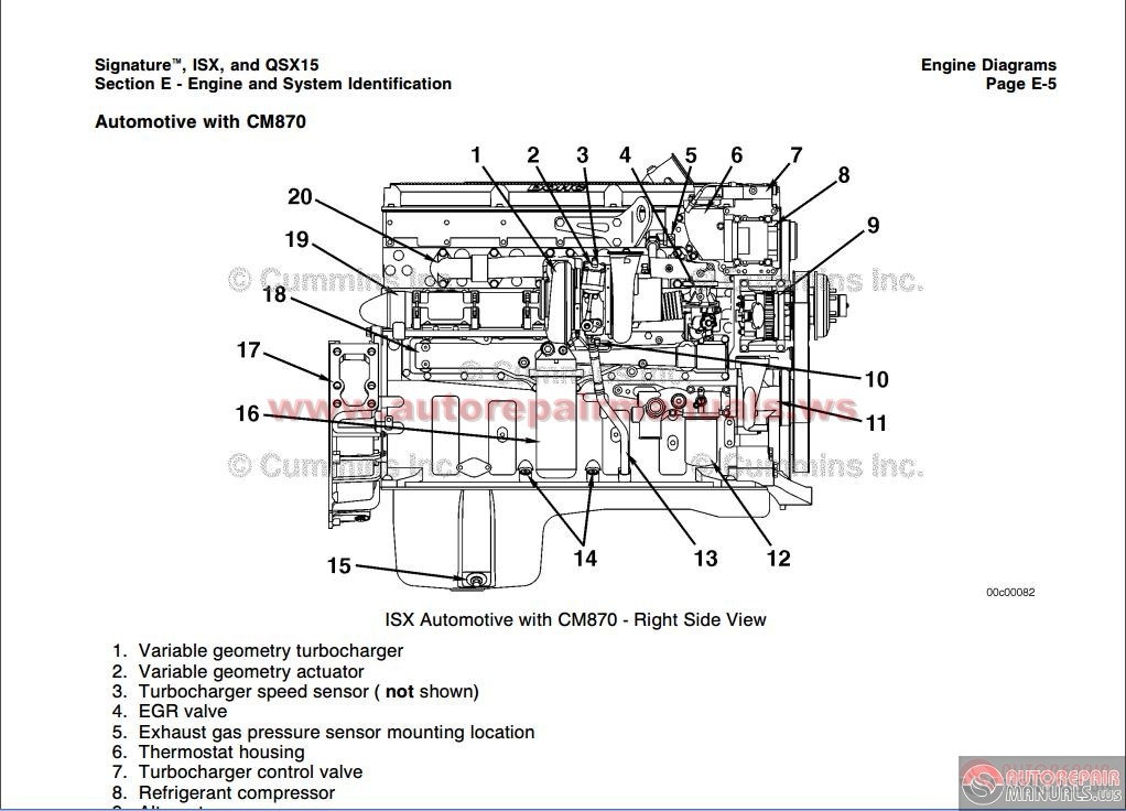
Isx Cummins Egr Valve Wiring Diagram
3400 V6 Engine Diagram Egr - Wiring Diagram Networks

HowTo Check EGR system

2000 Honda Accord Check Engine Light Egr Valve | Adiklight.co
94 S10 Egr Valve Wiring Diagram

EGR valve question - General Auto Repair Discussions at ...

1994 Ford F 150 Engine 5 8 Diagram - Wiring Forums

Toyota Prius c Gasket, egr cooler, no. 1. System, fuel ...

2005 Chevy Equinox Egr Retrofit Wiring Diagram
Mazda 6 Egr Wiring Diagram - Wiring Diagram

Wiring Diagram For 2006 Chevy Equinox Egr Valve - Wiring ...

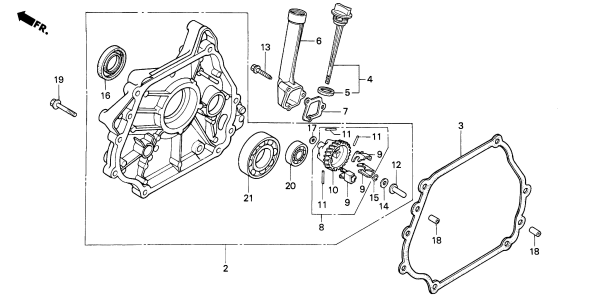
KA24E EGR valve exploded diagram | Custom car parts ...

I have a 2002 mercury sable 3.0 my chech engine keeps ...
Ford DPFE sensor and EGR System Ricks Free Auto Repair ...
0 Response to "37 egr valve wiring diagram"
Post a Comment