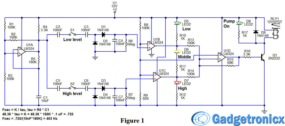
37 pump control panel wiring diagram schematic
Tal Engineering Vvvf Elevators Control Panels. 3 phase submersible pump control panel circuit diagram.It has inbuilt single phase. A wiring diagram is a streamlined standard pictorial depiction of an electric circuit. 240 volt well pump wiring diagram wiring diagram is a simplified all right pictorial representation of an electrical circuit it shows the components of the circuit. Interconnection wiring (schematic) diagram. ... the distribution panel or circuit breaker that supplies the pump control panel. C. Enclosure:.
#3838 Get Free ACCESS Wiring Diagram Databse ... wiring diagram mitsubishi l300 leewa car radio stereo wiring harness adapter for wiring diagram mitsubishi l300 wiring diagram mitsubishi l300 wiring diagram mitsubishi l300 workshop manual galant sears craftsman manual lawn mower wiring mitsubishi fuso electrical diagram sears craftsman manual lawn mower mitsubishi lancer ignition coil wiring diagram ford 2g alternator wiring harness sears craftsman manual lawn mower glow plug control module u2013 expert information sears craftsman manual lawn

Pump control panel wiring diagram schematic
#2973 Get Free ACCESS Wiring Diagram Databse ... diy how to change engine mounts mercedes mercedes wiring 2006 mercedes e350 fuse chart remove install audio gateway control unit agw n93 1 u2013 mb medic mercedes navigation upgrade becker map pilot u2013 mb medic 2001 power folding mirrors w212 e-class electrical diagram for w219 rear fuse panel video change serpentine poly v drive belt u0026 tensioner on mercedes air suspension strut airbag replacement diy u2013 mb fuse box lid schematic mercedes thermostat replacement diy guide u2013 mb medic Float Switch Installation Wiring Control Diagrams Apg. Single phase motors and controls submersible pump wiring diagram control microcontroller panel sheet colors symbols literature how to wire the mppt controller with soft starter for potable water well automatic full tornatech fire controllers booster overview eaton aeg washing machine of two pumps float switch installation motor circuit pdf ... Wiring diagrams show the components of a system as well as their connections. Whether it's a simple home appliance or a control panel wiring diagram, most systems and devices will include power supplies, a ground, and switches. Control panel diagrams, however, will feature relays, motor starters, alarms, relays, and pilot devices.
Pump control panel wiring diagram schematic. Dec 19, 2016 - A platform to learn electrical wiring, single phase, 3 phase wiring, controlling, HVAC, electrical installation, electrical diagrams. #216 Get Free ACCESS Wiring Diagram Databse ... 2004 nissan murano i took driver side door panel off and wiring diagram for murano fuel pump connector 24010 heated seats wiring diagram 2011 murano alternator wiring it has 3 wires yellow blue nimo le 2009 relay location i want to use the satellite prewired 16 pin connector 2009 nissan versa door lock wiring diagrams 2009 nissan murano alternator wiring diagram 24275 7 pole wiring diagram nissan frontier wiring for 2009 looking for info on how the wires that connect to the back i need a wiring page 26 — st4/st6 series submersible pumps • operation anD parts manual — rev. #1 (11/12/13). CONTROL BOX WIRING DIAGRAM (CB1269/CB1274). Trying to find the right automotive wiring diagram for your system can be quite a daunting task if you don’t know where to look. Luckily, there are some places that may have just what you need. Here’s where to start. Before you search for a...
Spi Bio Pump Control Panel With High Water Alarm Model 50b010 Whap Complete Panels Parts By Category Tg Wastewater. Pump alarm duplex septic sewage pumps tank alarms contractor talk aerobic system faqs q a on camden supply company inc control panels tran t2 panel aquaworx box controlonitor systems 220 wiring float switch setup for installation guide well diagnostics spi bio b double light sim ... Control Box Wiring Diagrams AND OTHER CONTROL RELAY. 1. 2. 5. RED. YEL. START CAP. MFD. V. RUN. Technicians should test a well pump's control box before pulling a nonworking pump from the well. Well pumps with control boxes have start and run circuits. Visually inspect the control panel's wires, wire connections, relay and capacitor . A wiring diagram generally gives info regarding the family member placement and plan of gadgets as well as terminals on the tools, to help in building or servicing the gadget. This is unlike a schematic diagram, where the arrangement of the elements' affiliations on the representation typically does not match to the elements' physical ... Apr 20, 2018 · pump control panel wiring diagram schematic – What’s Wiring Diagram? A wiring diagram is a schematic which uses abstract pictorial symbols showing each of the interconnections of components inside a system.
for 20mA. See the wiring diagrams (Figures 7 & 8) at the end of this manual for the proper wiring of the current transmitter. 2.0 APPLICABLE DOCUMENTS none 3.0 REQUIREMENTS 3.1 GENERAL DESCRIPTION The Duplex Pump Control System (CPC-2) is a system that automatically controls one or two pumps in pump down type applications. If electrical control panel is to be set remote from the pump sump, a NEMA 4 junction box should be used to make power and control connections. The HYDROMATIC NEMA 4 junction box is provided with compression connectors for sealing all wires. No sealing compound is needed to make connections waterproof. Wiring diagrams are provided with panel ... #530 Get Free ACCESS Wiring Diagram Databse ... 2002 ford explorer fuse box diagram needed 1997 ford explorer fuse box diagram 2002 ford explorer fuse box diagram needed 2002 ford explorer sport trac engine diagram 2001 ford explorer sport trac power mirrors fuses 2002 ford explorer fuse box diagram needed 2002 ford explorer xlt interior fuse box diagram 2001 ford explorer fuse box 2002 ford explorer fuse diagram 1996 ford explorer driver side low beam not working bulb 2002 ford explorer sport trac fuse panel diagnostic 2002 ford explorer spo Electrical Wiring Schematic. Jockey Pump Controllers. Technical Data TD081009EN. Single Phase. Effective June 2015. P1. P2 1 2 C C 3 4 5 6.
Use a three (3) or four (4) float operation to always run two pumps at a time where high flow is required (i.e. two lead pumps, and two lag pumps). Use a five (5) or six (6) float operation for true demand dosing and the control panels will operate as many pumps as required (i.e. one lead pump, and up to three lag pumps).
3 Phase Water Pump Control Panel Wiring Diagram. angelo on June 19, 2021. 3 Phase Wiring Diagram For House Http Bookingritzcarlton Info 3 Phase Wiring Diagram Fo Electrical Circuit Diagram Electrical Wiring Basic Electrical Wiring. Submersible Pump Control Box Wiring Diagram For 3 Wire Single Phase Submersible Pump Submersible Well Pump ...
NEMA and IEC Markings and Schematic Diagrams...... 4. Control and ... Overcurrent Protection for 3-Wire Control Circuits ... Lettered Terminals in Panel.
In this tutorial, we will show the Star-Delta (Y-Δ)Starting Method by Automatic star-delta starter with Timer with schematic, power, control and wiring diagram as well as how star-delta starter works and their applications with advantages and disadvantages. Explanation of the working and operation of Star Delta Automatic...
Connect the wires coming from the pumps to the pump terminals. Refer to the panel wiring diagram for the correct terminal connections for your system. 3. Connect the incoming power to the panel. Power to the panel must be appropriate to the control panel and pump motor (120 VAC, single-phase for a 120 VAC motor, 240 VAC single-phase for a 240
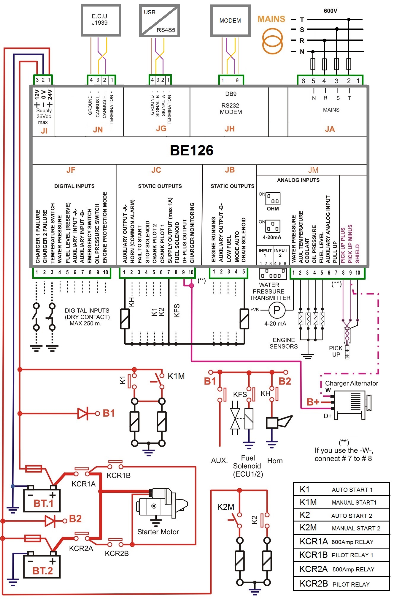
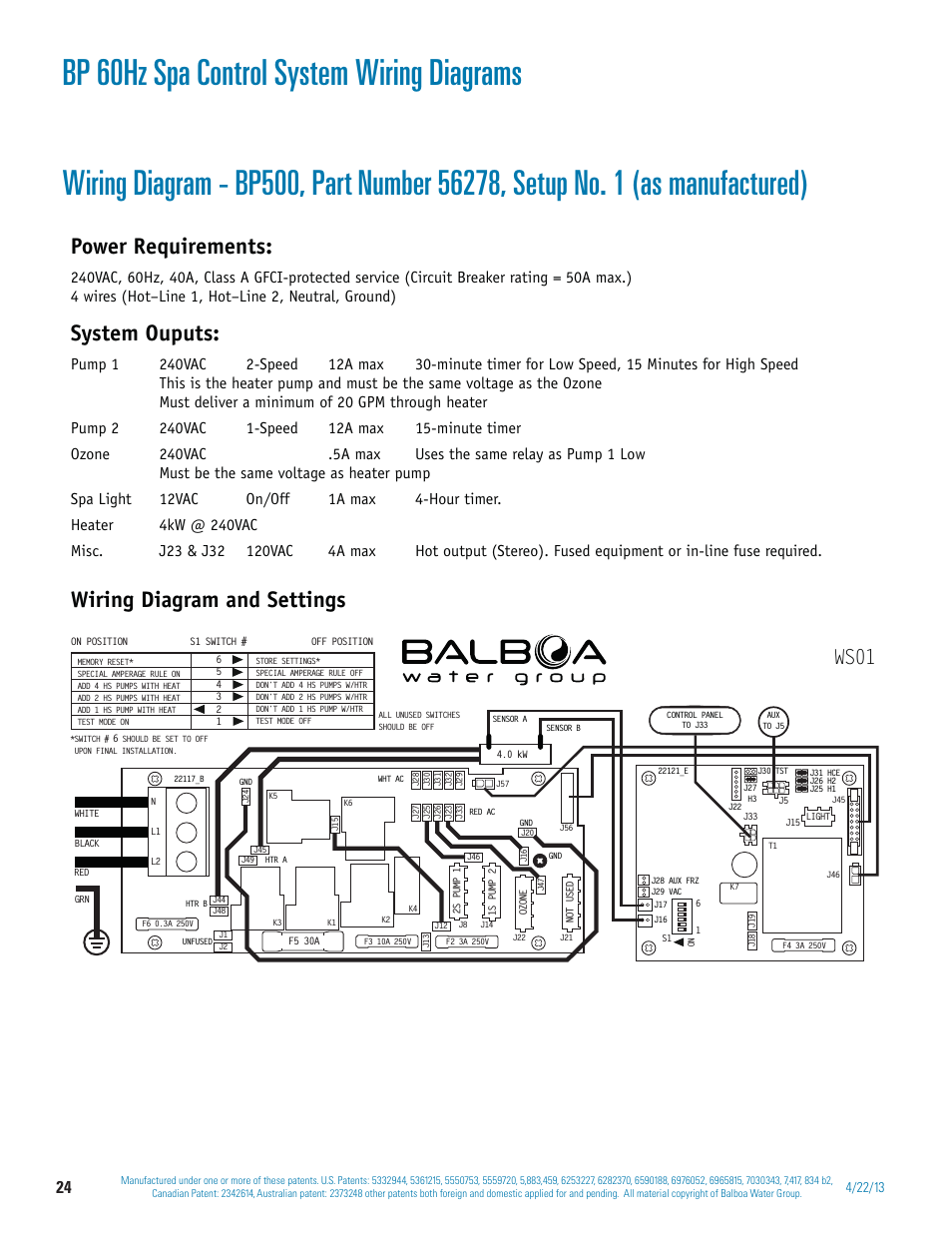
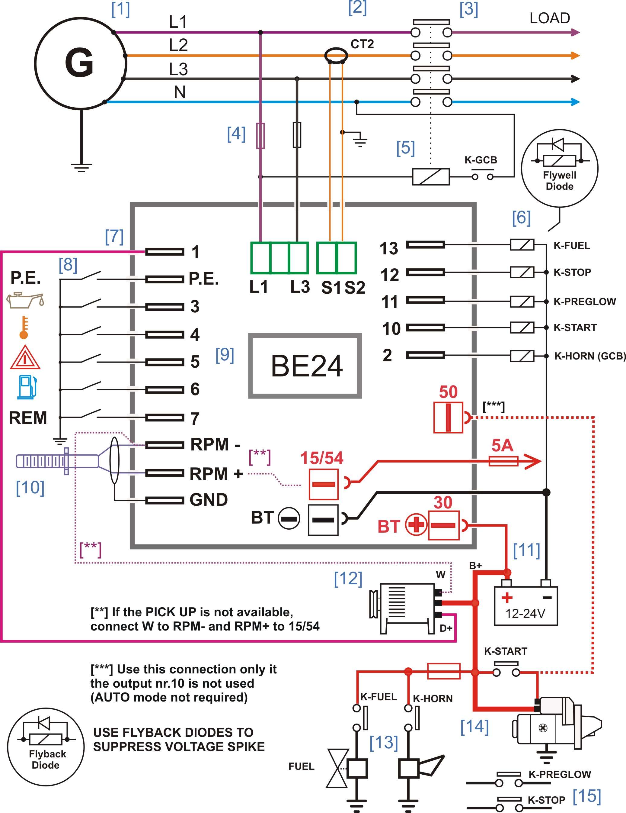
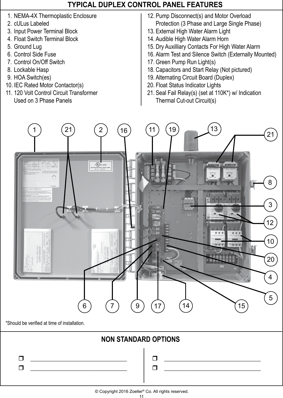
Pump Control Panel Wiring Diagram Schematic – wiring diagram is a simplified conventional pictorial representation of an electrical circuit. It shows the components of the circuit as simplified shapes, and the capability and signal associates amid the devices. A wiring diagram usually gives guidance roughly the relative face and concord of ...
#3407 Get Free ACCESS Wiring Diagram Databse ... 1968 mustang wiring diagrams evolving software painless fuse relay box install switched relay dual horns - mc how-to 1965 chevrolet chevy ii wiring diagram 67 camaro headlight wiring diagram what to look for 1968 camaro replaced all wiring w new no radio no turn signals - 1971 1971 ford half ton wiring diagram 67 mustang ignition switch wiring diagram 1998 chevrolet suburban 1500 wirng diagram 72 nova wiring schematic mitsubishi manual engine 6d22 manual basic headlight wiring diagram motorcycle
V10-T6-4 Volume 10—Enclosed Control CA08100012E—November 2012 www.eaton.com 6 6 6 6 6 6 6 6 6 6 6 6 6 6 6 6 6 6 6 6 6 6 6 6 6 6 6 6 6 6 6.1 Pump Panels Industrial Pump Panels Catalog Number Selection Pump Panel Notes 1 More information on Type 1, 3R, 4X and 12 duplex pump panels is on Page V10-T6-23.Product Selection is on Page V10-T6-26. 2 For other voltages and single-phase applications ...
codes. Requirements may vary depending on usage and location. See wiring diagrams in manual. 39. Do Not operate the pump in the “HAND” control position and leave the pump unattended. 40. CAUTION - This unit may have more than one connection to the source of supply. To reduce the risk of electric shock, disconnect all such connections before ...
Control Panel Wiring | Pump Control Panel Wiring Diagram | How to read Single Line DiagramIn this video you will learn about Control Panel ...
Components Disconnects (Fuse vs. Breakers) Generator Provisions Motor Protection (Fuses, Breakers, Thermal) Motor Controls (Starters, Soft Starters, Drives) Transformers Logic (Relay, Controllers, PLC) Alarm Dialers / Telemetry Pilot Devices Intrinsically Safe
#2260 Get Free ACCESS Wiring Diagram Databse ... three phase motor connection star delta y how to select contactors for use in direct on line starters star-delta starter star delta starter timer off power and wiring control electrical engineering world six ways to wire star electrical diagrams phase motor connection 1970 bus wiring diagram dol starter operation and control wiring animation video electrical page single phase motor contactor wiring diagram three phase to single phase conversion of an old uni electrical engineering world ground f
IDENTIFICATION OF BARNES STEALTH SERIES DUPLEX CONTROL PANEL FOR ESPS-200 LEVEL CONTROL WIRING To determine the proper wiring schematic you will need to fi rst determine the panel type you have using the information listed below. The information can be located inside the control panel door on the panel schematic.
Note: In this publication the line diagrams show the control circuits only - power circuits are omitted for clarity, since they can be traced readily on the wiring diagrams (heavy lines). A wiring diagram gives the necessary information for actually wiring-up a group of control devices or for
#3493 Get Free ACCESS Wiring Diagram Databse ... wiring diagrams for a ceiling fan and light kit bathroom gfci wiring diagram wiring schematic bathroom light how to wire bathroom fan with light electrical switch wiring red black white electrical switch wiring red black white mgb wiring diagram how to install ceiling fan in recessed light unique payne gas furnace wiring diagram diagram electrical wiring diagram light switch #3493 Diagram Database p320diagrams.racingportuense.es HOME p320diagrams.racingportuense.es Button Wire Diagram Toyota Ter
(Example: All components and wiring schematics for the engine control system would appear in one section, with off-page references to other sections when... This location information enables the technician to quickly locate the electrical component referenced in the schematic; and it is shared between all Wiring Diagrams for...
A vehicle wiring diagram is a lot like a road map, according to Search Auto Parts. Wiring diagrams are laid out similar to a road map because the diagrams show how each major electrical system, individual circuit and sub-system connects, th...
Sep 24, 2021 · If a control panel is not used a stand alone high liquid level alarm is avail able. Pump control panel wiring diagram schematic Collection Emerson Pump Motor Wiring Diagram Car Control Panel Schematic Soft. A wiring diagram is an easy visual representation in the physical connections and physical layout of an electrical system or circuit.
Control voltage is 120 VAC · Use IEC devices · 22mm pilot devices · Wallmount enclosure – outdoor rated · Main circuit breaker with door mounted operating handle ...
Pump Control Panel Wiring Diagram Schematic. Assortment of pump control panel wiring diagram schematic. A wiring diagram is a simplified traditional photographic depiction of an electric circuit. It shows the parts of the circuit as simplified shapes, as well as the power as well as signal links between the devices. A wiring diagram typically provides info…
accesstopower, #motorcontrolIn this video, we will look at the control wiring for a 3 phase pump panel and how a pump is controlled both in ...
Jan 18, 2022 · Pump control panel wiring diagram schematic. It shows the elements of the circuit as streamlined forms, and the power and signal connections in between the devices. Find all Fire Pump Controller drawings as well as Jockey Pump Controller, Remote Alarm Panel, and Low Suction Shutdown Controller drawings here..
Aquaworx Septic Pump Control Box Infiltrator. Spi Bio B Double Light Control Panel For Aerobic Septic Systems 50b006 Tg Wastewater. Float Switch Installation Wiring Control Diagrams Apg. Spi Bio Pump Control Panel With High Water Alarm Model 50b010 Whap Tg Wastewater. Indoor Tank Alarm High Water No Float Only Battery Backup.
2-wire well pump diagrams are slightly easier to understand, and are more straight-forward to wire. Black wires go to black wires, and the green wire (the ground) goes to the ground wire. Fig. 1 (Above): 2 Wire Well Pump Wiring Diagram . Three-Wire Well Pump Wiring Diagrams. 3-wire well pump diagrams are more complicated and require a better ...
B. Electrical schematic shall be plastic laminate affixed inside the control panel door. C. Electrical control panels shall be of sufficient size to house all control equipment. All panel penetrations for conduit shall be from the bottom. D. A double throw walking beam transfer switch shall be mounted inside the main control panel.
#3092 Get Free ACCESS Wiring Diagram Databse ... kawasaki 750 zxi 1995 zxi750 cdi ignitor 21119 96 kawasaki 750 zxi trim was bad replaced motor still 1100 1200 electrical control box diy kit 3 pole contactor wiring diagram some kz 400 500 550 wire diagrams kawasaki bayou wiring harness 1995 kawasaki mule wiring diagram suzuki gs 750 motorcycle service manual 1977 #3092 Diagram Database elenora.racingportuense.es HOME elenora.racingportuense.es Dodge Ram 2500 Trailer Wiring Diagram Almera N16 Wiring Diagram Pontiac G6 Wiring Diagram Abs Toyota
Ability to diagram at the Block, Icon, System, or Schematic level. A library of over 700 generic symbols, as well as custom symbol creation. Access to over 4 million components via Digi-Key Catalog integration. Freedom to keep designs private, make public, share via link, or embedded into web pages, blogs or emails. Rapid...
Two-Wire Control Two-Wire Control circuits — or Low Voltage Release One of the common control wiring circuits used is known as Two-Wire or Low Voltage Release (LVR). It utilizes a main-tained contact type of pilot device — such as a thermostat, float switch or presence sensor. Figure 6 shows the line and wiring schematics for this circuit.
May 06, 2019 · Wiring diagrams for all control and electrical panels. Diagrams shall (e) Electrical schematic diagram of the pump station as supplied, prepared in. Economy Duplex Sump Pump Control The duplex control provides alternating operation of two volt pumps. Plug-in ready wiring makes installation easy! Simply plug the pumps into the provided receptacles.
4. Locate the booster pump control on a wall as close to the booster pump system as possible. 5. Follow all local plumbing and electrical codes. After guidelines have been met, connect the booster pump wiring to the motor contractor located in the control panel (ref control wiring diagram in the control panel).
#1530 Get Free ACCESS Wiring Diagram Databse ... western unimount wiring diagram wrud 3342 stair lift wiring diagrams get wiring diagrams boat lift motor wiring diagram sample wiring u0026 installation upright scissor lift wiring diagram 2 post lift wiring diagram download ricon s series wheelchair lift wiring diagram collection 32 rotary lift wiring diagram lift ergonomic scissor lift wiring schematic collection of elevator wiring diagram pdf sample crow river wheelchair lift wiring diagram download snorkel lift wiring diagram lift axle wirin
A home or vehicle is a maze of wiring and connections, making repairs and improvements a complex endeavor for some. Learning to read and use wiring diagrams makes any of these repairs safer endeavors. These simple visual representations all...
pumps and control circuit or the control circuit can be wired to a separate power supply to insure alarm integrity in case of a tripped main breaker. ... • Field wiring diagram, panel schematic and installa-tion instructions included.
Wiring diagrams show the connections to the controller, while line diagrams show circuits of the operation of the controller. Standardized symbols.
https://ryb.com.bd/ 3 Phase DOL Starter Control and Power Wiring Diagram! water Pump Controller with float switchauto manual connection of water pump motor w...
#540 Get Free ACCESS Wiring Diagram Databse ... electro help daewoo matiz car daewoo car radio stereo audio wiring diagram diagram daewoo kalos wiring diagram full version hd daewoo matiz car wiring diagram electro help daewoo matiz car daewoo service manual engine control matiz daewoo cielo ignition module connection daewoo matiz new daewoo matiz immobiliser reset daewoo lanos electrical wiring diagram service manual daewoo daewoo matiz euro iii 2003 engine compartment electrical new daewoo matiz immobiliser reset daewoo nexia cielo racer ii
INSTALLATION WIRING DIAGRAM - 115VAC - TWO-WIRE PUMPS For 115 Vac motors exceeding 16 full load amps, use magnetic starter to avoid damage toMascontrol®. See separate magnetic starter wiring diagram.! WARNING 22 Remove pressure switch from surface pump and wire Mascontrol® directly to pump. IMPORTANT

![[XE_8154] 2006 Cobalt Transmission Wiring Diagram Download ...](https://static-resources.imageservice.cloud/1289640/2006-cobalt-will-not-start-after-a-cranking-battery-voltage-test-i.gif)

![[VZ_2410] Wiring Diagram For Elevator Free Diagram](https://static-assets.imageservice.cloud/118064/single-phase-water-pump-control-panel-wiring-diagram-basic.jpg)











0 Response to "37 pump control panel wiring diagram schematic"
Post a Comment