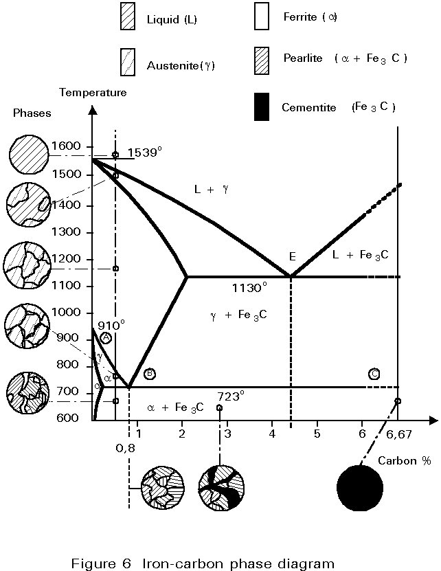
42 iron carbon equilibrium diagram
There is also a spectrum of biospheric carbon sequestration methods, such as enhancing oceanic plankton productivity by iron fertilization, reforestation or altering forestry and agricultural management practices to maximize carbon stored in soil and vegetation, but the potential and permanence of these biospheric techniques... Answer: The iron-carbon diagram (also called the iron-carbon phase or equilibrium diagram) is a graphic representation of the respective microstructure states depending on temperature (y axis) and carbon content (x axis). The melt essentially cools via the austenite to ferrite phases - i.e. from...
The Iron Carbon Phase Diagram · A : The temperature where iron looses its magnetism (so-called Curie temperature). · A : The boundary between the γ austenite ...
Iron carbon equilibrium diagram
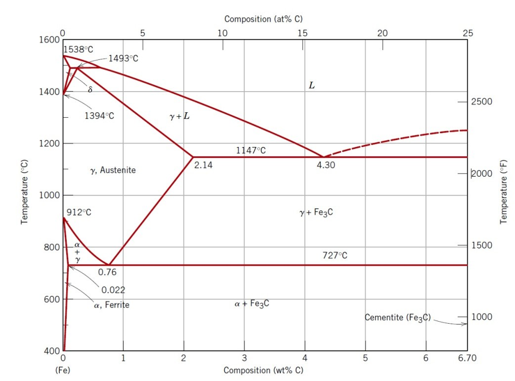
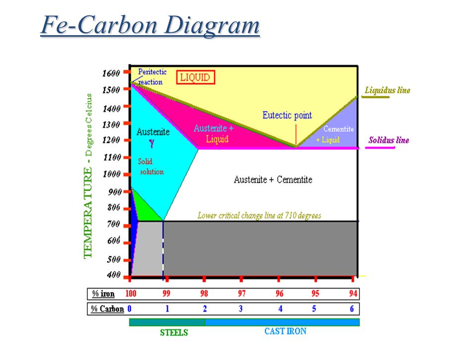
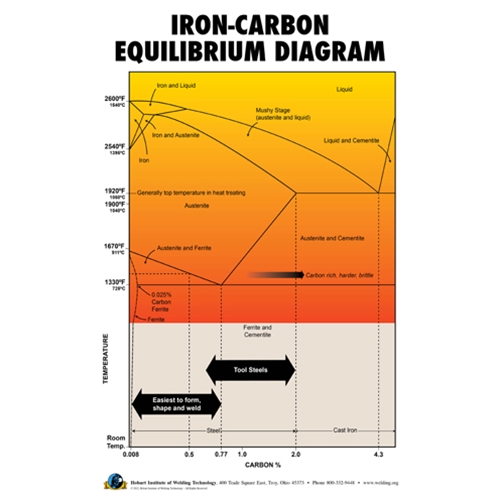
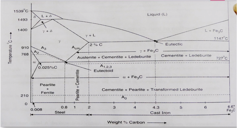
Iron-Carbon Phase Diagram with Detailed Explanation: If the percentage of the carbon is in the range of 0 to 2.11 % then it is called Steel and if the percentage of carbon is in the range of 2.11 to 6.67% then it is called Cast iron. As the carbon content increases, it produces more Iron-Carbide volume and that phase will exhibit high hardness. The iron -carbon phase diagram in Fig 2 actually shows two diagrams namely (i) the stable iron-graphite diagram (red lines), (ii) and the metastable Fe-Fe3C diagram. Cementite is metastable, and the true equilibrium is to be between iron and graphite (C). Stability-field diagram for aqueous ferric-ferrous system _.__ 5 2. Relation of total activity of iron in water to pH and Eh__ ___ 11 TABLES TABLE 1. Equilibrium constants_____________________________--__-__ 3 2. Free energy data___________._______________________--_--_ 4 3. Eh, pH, and ferrous ion concentration measurements on...
Iron carbon equilibrium diagram. Cementite or iron carbide, is very hard, brittle intermetallic compound of iron & carbon, as Fe 3 C, contains 6.67 % C. It is the hardest structure that appears on the diagram, exact melting point unknown. Its crystal structure is orthorhombic. It is has low tensile strength (approx. 5,000 psi), but high compressive strength. We have used density functional theory (DFT) to investigate the ternary phase diagram of the Li−Fe−F system and the reactions of Li with iron fluorides. Several novel compounds, not previously identified in the Li−Fe−F system, are predicted to be stable. Electrochemical voltage profiles, derived from the evolution of... The iron-carbon diagram provides a valuable foundation on which to build knowledge of both plain carbon and alloy steels in their immense variety. Fig. 1. The iron-carbon diagram. It should first be pointed out that the normal equilibrium diagram really represents the metastable equilibrium between iron and iron carbide (cementite). The iron-carbon diagram assumes a constant cooling of the metals. If the metal is slowly cooled down, coarse grains are formed. If the metal is cooled down quickly, fine-grained metal is the result. The type of metal grain determines the strength properties. Coarse grain has a lower strength, but can be made finer-grained and therefore stronger ...
Phase Diagrams Module-07 1) Equilibrium phase diagrams, Particle strengthening by precipitation and precipitation reactions 2) Kinetics of nucleation and growth 3) The iron-carbon system, phase transformations 4)... Thus Condensed Gibbs phase rule is written as: 2CFP 1CFP Equilibrium phase diagram A diagram that depicts... The iron-carbon diagram (also called the iron-carbon phase or equilibrium diagram) is a graphic representation of the respective microstructure states depending on temperature (y axis) and carbon content (x axis). The actual iron-carbon diagram is far larger than the part shown here. 4 CHEMICAL EQUILIBRIUM BETWEEN IRON, CARBON, AND OXYGEN If a solid phase containing an excess of free carbon is subjected to a certain temperature in vacuo, an equilibrium is established when each of the reactions and Fe304 + CO - 3FeO + C02 2C0 —s C + C02 has acquired equilibrium at that temperature. The equilibrium condi- Oct 11, 2017 · IRON CARBON EQUILIBRIUM DIAGRAM, TTT DIAGRAM AND HEAT TREATMENT 1. IRON CARBIDE DIAGRAM TTT DIAGRAM & HEAT TREATMENT By: Ankit Saxena 2. IRON-C phase diagram 3. From previous fig of FE-C diagram 4. • Hypo-eutectoid steels: Steels having less than 0.8% carbon are called hypo-eutectoid steels (hypo means "less than").
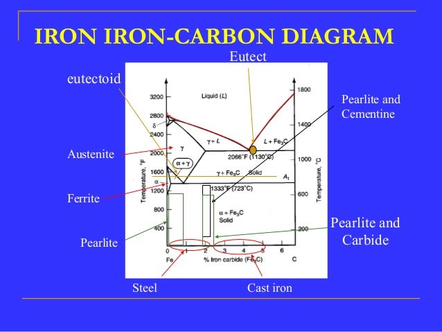
Definition of structures Various phases that appear on the Iron-Carbon equilibrium phase diagram are as under: •Austenite •Ferrite •Pearlite •Cementite •Martensite* •Ledeburite 6. Unit Cells of Various Metals FIGURE - The unit cell for (a) austentite, (b) ferrite, and (c) martensite. The effect of the percentage of carbon (by weight ... Iron-Cementite diagram is not a true equilibrium diagram, since equilibrium means no change of phase with time, however long it may be. Graphite is more stable form of carbon. Cementite is a metastable phase, which decomposes to graphite if given long periods of time. Graphitisation, however, rarely occurs in steels and may take years to form. 3.1 THE IRON-CARBON EQUILIBRIUM DIAGRAM. A study of the constitution and structure of all steels and irons must first start with the iron-carbon equilibrium diagram. Many of the basic features of this system (Fig. 3.1) influence the behaviour of even the most complex alloy steels. For example, the phases found in the simple binary Fe-C system ... Zirconium-gadolinium Equilibrium Diagram Mark I. Copeland · Clo E. Armantrout · H. Kato 1961년 1월 · U.S. Department of the Interior, Bureau of Mines eBook 13 페이지 무료 eBook eBook 정보 arrow_forward null 책 평가하기 의견을 알려주세요. 리뷰 작성하기 읽기 정보 expand_more ...
Iron-Carbon Phases | Metallurgy for Dummies
A scheme of mono- and nonvariant equilibrium in the system Fe-C-V that takes into account the relation of this system with the systems Fe-C and V-C is obtained.... For steels they allow to optimize the content of carbon and vanadium ensuring the effect of dispersion strengthening and the selection of heat treatment conditions....
What is the use of an iron carbon diagram? - Quora
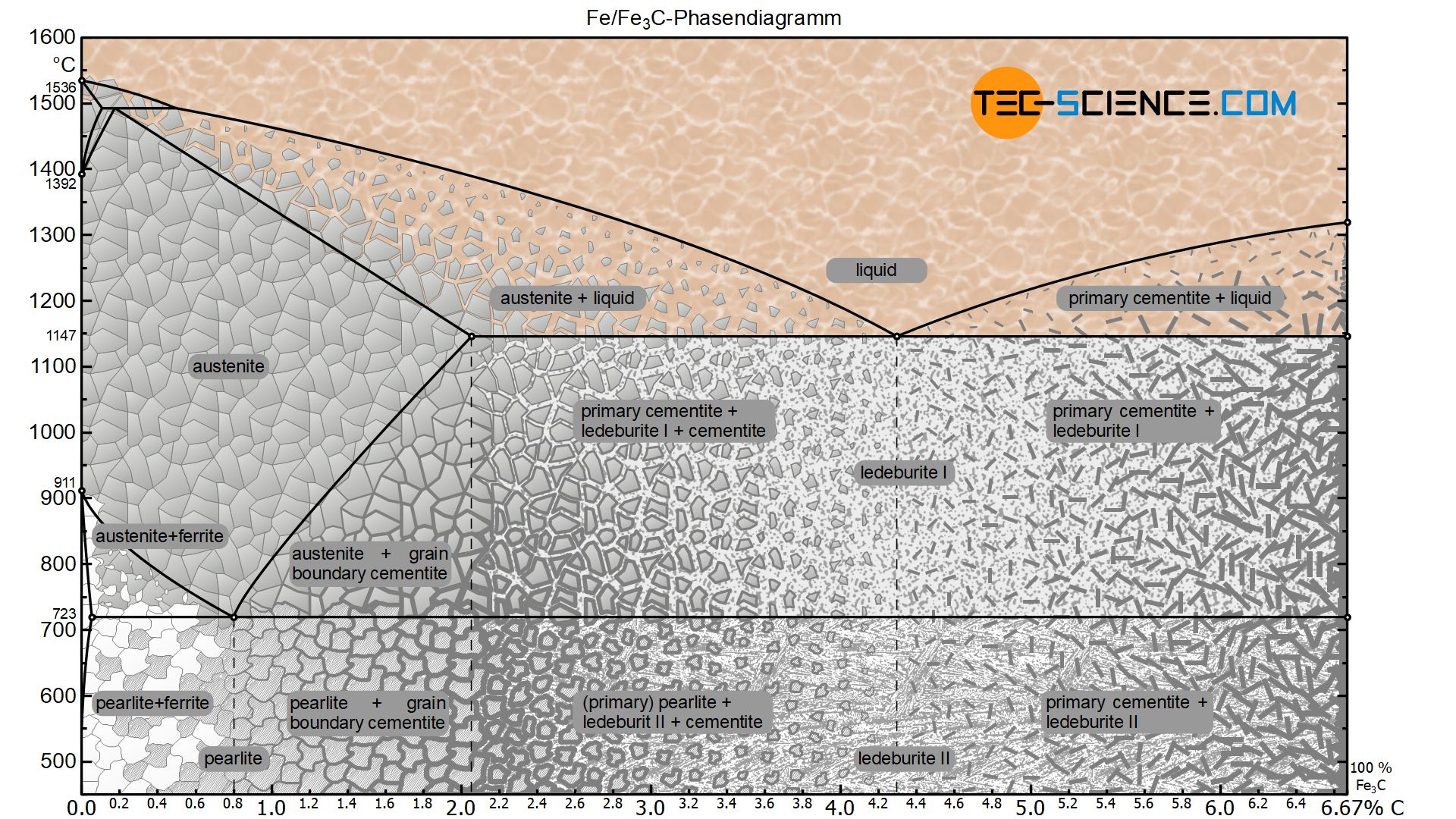
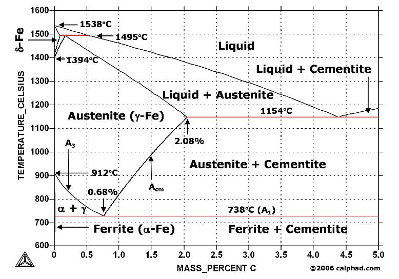
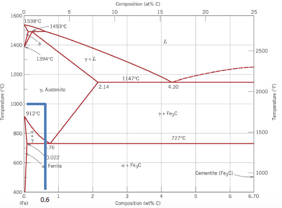
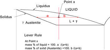
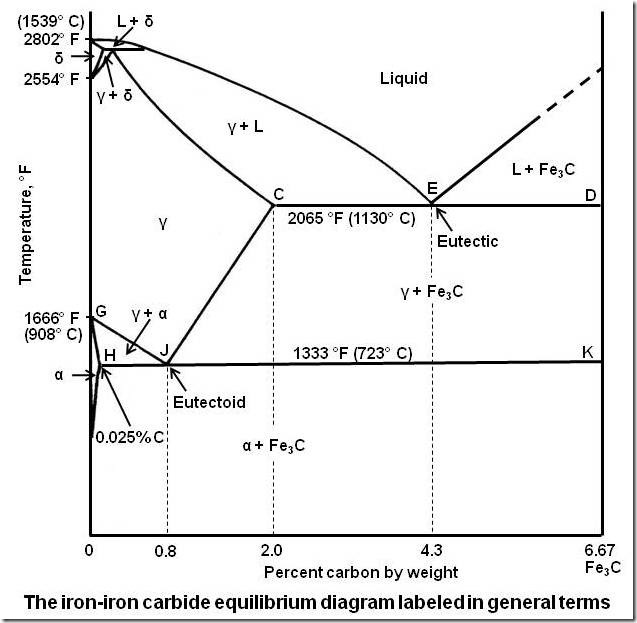
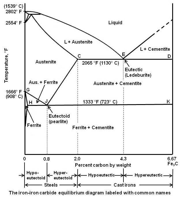
Click to see full answer Correspondingly, what is eutectic reaction in iron carbon diagram? Eutectic Reaction • Eutectic reaction: at 4.30 % C and 1147 °C L (4.30% C) ↔ γ (2.14% C) + Fe3C • In eutectic reaction, the liquid solidifies as a phase mixture of austenite (containing 2.14% C) and cementite.This phase mixture is known as ledeburite.

MECHANICAL FUNDAS: IRON IRON CARBIDE EQUILIBRIUM DIAGRAM
Nov 28, 2021 · The Iron carbon equilibrium diagram (also called the iron carbon phase diagram) is a graphic representation of the respective microstructure states of the alloy iron – carbon (Fe-C) depending on temperature and carbon content. The iron carbon phase diagram is commonly used to fully understand the various phases of steel and cast iron.

Figure 15-11.--Iron-carbon phase diagram.
Fe-C Phase diagram (Part of the Iron-Carbon phase diagram is shown below) c) What is the %wt content of eutectoid phase if the material is cooled slowly? ... Using the phase diagram above, describe what would happen if the steel where cooled under equilibrium conditions from 900°C. Rockwell C hardness 40 30 0 1.2 0.2 0.4 0.6 0.8 1.0 Weight ...

Can Someone Explain Me About This Iron - Carbon Phase Diagram ...
FactSage Thermochemical Database System ... FactSage Representatives around the world FactSage Courses / Workshops : | Feb. 14 - 17 2022, Germany (online) FactSage online course | | Feb. 21 - 25 2022, South Korea (online workshop) FactSage workshop | | 2021 CRCT Research day and mini FactSage workshop - click HERE for recordings | Introduction Database Documentation FactSage Applications Posters and Publications Ordering and Representatives Phase Diagrams & Documentation Download FactSage Products CRCT Clients Fact-Web Free FactSage Demo
Determination of microstructure and phase fractions in steels ...
Feb 12, 2016 · Cementite is a chemical compound of carbon with iron and is known as iron carbide (Fe3C). Cast iron having 6.67% carbon is possessing complete structure of cementite. Free cementite is found in all steel containing more than 0.83% carbon. It increases with increase in carbon % as reflected in Fe-C Equilibrium diagram. It is extremely hard.
phase diagram iron carbon | Metallurgy for Dummies
The iron-carbon diagram was investigated at a pressure of 90 kbar and concentrations of 25-40 at% C by metallographic and x-ray methods. The formation of the... It is shown that the equilibrium between the melt, Fe//3C and Fe//7C//3 is of peritectic type, with the interaction occurring between the liquid, Fe//7C//3, and...
![Iron-Carbon equilibrium diagram [62] | Download Scientific ...](https://www.researchgate.net/profile/Ashwin-Polishetty/publication/268747490/figure/fig11/AS:670010443833358@1536754346351/Iron-Carbon-equilibrium-diagram-62.png)
Iron-Carbon equilibrium diagram [62] | Download Scientific ...
The iron-carbon diagram provides a valuable foundation on which to build knowledge of both plain carbon and alloy steels in their immense variety. Fig. 1. The iron-carbon diagram. It should first be pointed out that the normal equilibrium diagram really represents the metastable equilibrium between iron and iron carbide (cementite).
Why is the carbon percentage of the iron-carbon equilibrium ...
This iron carbon phase diagram is plotted with the carbon concentrations by weight on the X-axis and the temperature scale on the Y-axis. The carbon in iron is an interstitial impurity. The alloy may form a face centred cubic (FCC) lattice or a body centred cubic (BCC) lattice. It will form a solid solution with α, γ, and δ phases of iron.
What are the advantages of iron carbon equilibrium diagram ...
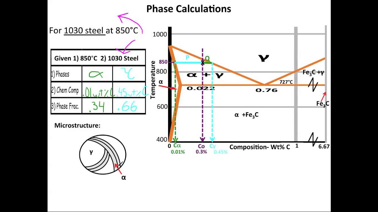
Iron-Carbon Equilibrium Diagram | Metallurgy Hypereutectoid steel: has a carbon content greater than the eutectoid 8 Example: Phase Equilibria For a 99.6 wt% Fe-0.40 wt% C at a temperature just below the eutectoid, determine the following a) composition of Fe 3C and ferrite (α) b) the amount of carbide (cementite) in grams that forms

Iron–carbon equilibrium diagram for decarburization under ...
The part of iron-carbon alloy system diagram between pure iron and an interstitial compound, iron carbide (Fe 3 C), containing 6.67 percent carbon by weight is called iron-iron carbide equilibrium diagram. It may be noted that though it is called as equilibrium diagram, it is not a true equilibrium diagram, since equilibrium implies no change ...

Who drew the iron carbon equilibrium diagram for the first ...
We propose that this behavior can be rationalized in terms of kinetically accessible pathways, which we discuss in the context of the bulk iron–carbon phase diagram with the inclusion of phase equilibrium lines for metastable Fe 3C. Our results indicate that kinetic effects dominate the complex catalyst phase evolution during...

Iron Carbon phase diagram | Download Scientific Diagram
Martensite (non equilibrium BCT phase from quench of γ) BCC Orthorhombic Iron/Carbon Phase Diagram Iron shows a eutectic with Carbon allowing for a lower melting alloy Body Centered Tetragonal. 6. 7. 8 Carbon content can be reduced by reaction with oxygen and stirring. 9. 10 Eutectoid Steel Pearlite. 11
Iron-Carbon Phase diagram [12] | Download Scientific Diagram
The iron-carbon diagram provides a valuable foundation on which to build knowledge of both plain carbon and alloy steels in their immense variety. A study of ...

TPCE Mech Books: IRON CARBON Phase Diagram or Equilibrium Diagram
Biomass in a low-carbon economy Committee on Climate Change November 2018 Acknowledgements 1... A number of organisations and stakeholders for their support, including Carbon Disclosure Project, Dr Sam Cooper... gsi.gov.uk 2 Biomass in a low-carbon economy | Committee on Climate Change Contents The Committee 3...

3 The true equilibrium iron-carbon phase diagram with ...
Click to see full answer Likewise, what is eutectic reaction in iron carbon diagram? Eutectic Reaction • Eutectic reaction: at 4.30 % C and 1147 °C L (4.30% C) ↔ γ (2.14% C) + Fe3C • In eutectic reaction, the liquid solidifies as a phase mixture of austenite (containing 2.14% C) and cementite.This phase mixture is known as ledeburite.
Consider Iron-carbon phase diagram given below: (a) | Chegg.com
The iron-iron carbide (Fe-Fe 3C) phase diagram Ferrite-α-BCC, low C solubility(0.022%wt), magnetic Austenite-γ-FCC, high C solubility(2.14%wt), nonmagnetic Ferrite-δ-BCC ... Microstructure in iron-carbon alloys Eutectic--pearlite Hypoeutectoid alloys Hypoeutectoid steel: has a carbon concentration less than the eutectoid. 4
Iron Phase Diagram - Roy Mech
Cast iron having 6.67% carbon is possessing complete structure of cementite. Free cementite is found in all steel containing more than 0.83% carbon. It increases with increase in carbon % as reflected in Fe-C Equilibrium diagram. It is extremely hard. The hardness and brittleness of cast iron is believed to be due to the presence of the cementite.
Using the Iron carbon phase diagram, identify the | Chegg.com
Jun 1, 2012 — Iron-carbon phase diagram describes the iron-carbon system of alloys containing up to 6.67% of carbon, discloses the phases compositions and ...

The Iron Carbon Phase Diagram
The second class of models invokes the differing volatilities of iron and sili- cates to fractionate the two phases [4,10-12]. Both equilibrium condensation [4] and vaporization [10-12] models are included within the second class. oo12-821x/87/$o3.5o © 1987 Elsevier Science Publishers B.V. The relative merits and demerits of...
Fe-Carbon Phase Diagram - ppt video online download
Iron carbide equilibrium diagram shows us metastable conditions, one can achieve equilibrium changes under slow heating and cooling. Importance of Iron Carbon Equilibrium Diagram According to the requirements of different applications, we can develop new alloys by handing them at different temperatures and changing the compositions of carbon in it.

Iron-Carbon Equilibrium Phase Diagram ... | Materials ...
Iron Carbide Equilibrium Diagram/ Material Science / Engineer's AcademyHello Everyone Welcome To AIM AMIEIn this videos we have covered the Iron Carbon Equil...

Please answer the following question regarding the iron-iron ...
Although it is heterogeneous, these phases behave like homogeneous pure bodies. Steel is between 0 and 2.06 mass percent of carbon. Cast iron is between 2.06 ...
3 The true equilibrium iron-carbon phase diagram with ...
Although it is heterogeneous, these phases behave like homogeneous pure bodies. Steel is between 0 and 2.06 mass percent of carbon. Cast iron is between 2.06 ...
Iron-Carbon Equilibrium Diagram Poster
CARBON DIOXIDE CAPTURE AND STORAGE Intergovernmental Panel on Climate Change CARBON DIOXIDE CAPTURE AND STORAGE This Intergovernmental Panel on Climate Change... The IPCC Special Report on Carbon Dioxide Capture and Storage provides invaluable information for researchers in environmental science, geology, engineering and the...

Iron-carbon phase diagram sectioned at 2 percent silicon ...
What is the iron carbon equilibrium diagram? The part of iron-carbon alloy system diagram between pure iron and an interstitial compound, iron carbide (Fe3C), containing 6.67 percent carbon by weight is called iron-iron carbide equilibrium diagram. In fact, the compound iron carbide decomposes into iron and carbon (graphite).
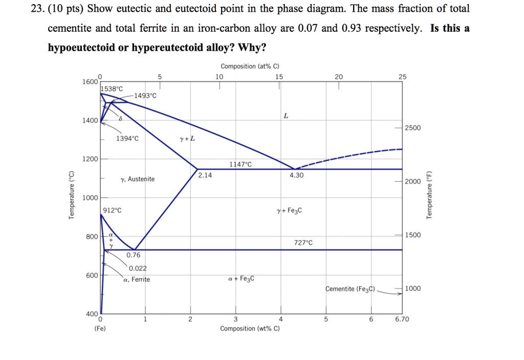
SOLVED:23. (10 pts) Show eutectic and eutectoid point in the ...
The Fe-C phase diagram is a fairly complex one, but we will only consider the steel part of the diagram, up to around 7% Carbon. University of Tennessee, Dept. of Materials Science and Engineering 2 MSE 300 Materials Laboratory Procedures Phases in Fe-Fe3C Phase Diagram ¾ α-ferrite - solid solution of C in BCC Fe • Stable form of iron at ...
Muddiest Point- Phase Diagrams V: Fe-Fe3C Microstructures
Why adding just a small amount of carbon to iron results in an alloy that is so much stronger than the base metal? In this course, you will learn how a material’s properties are determined by the microstructure of the material, which is in turn determined by composition and the processing that the material has undergone. This...
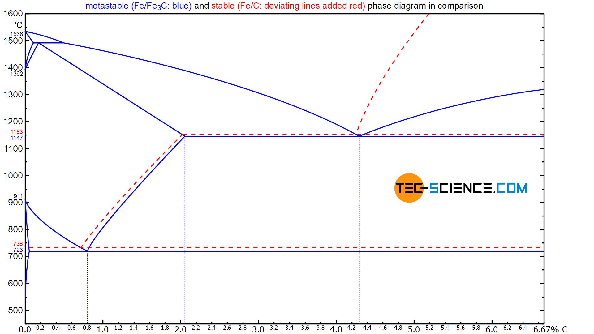
Cast iron - tec-science
Carbon dioxide appears as a colorless odorless gas at atmospheric temperatures and pressures. Relatively... Carbon dioxide is a one- compound with formula CO2 in which the is attached to each atom by a double bond. A... It is a one- compound, a gas molecular entity and a carbon oxide. Carbon Dioxide is a colorless, odorless...
Practical Maintenance » Blog Archive » The Iron-Iron Carbide ...
The calcuim treatment is necessary before the addition of magnesium since the latter also has an affinity for both sulphur and oxygen, whereas its spheroidising ability depends on its presence in solution in the liquid iron. The magnesium is frequently added as an alloy with iron and silicon (Fe-Si-Mg) rather than as pure...
![Iron-Carbon Phase Diagram Explained [with Graphs]](https://fractory.com/wp-content/uploads/2020/03/Iron-carbon-phase-diagram-explained.jpg)
Iron-Carbon Phase Diagram Explained [with Graphs]
This video will clear all your questions regarding Iron Carbon equilibrium diagram. Explained in tamil.This will give you clear idea about the phase changes ...

Figure 6 from Structure/Property Relationships in Irons and ...
Stability-field diagram for aqueous ferric-ferrous system _.__ 5 2. Relation of total activity of iron in water to pH and Eh__ ___ 11 TABLES TABLE 1. Equilibrium constants_____________________________--__-__ 3 2. Free energy data___________._______________________--_--_ 4 3. Eh, pH, and ferrous ion concentration measurements on...
Practical Maintenance » Blog Archive » The Iron-Iron Carbide ...
The iron -carbon phase diagram in Fig 2 actually shows two diagrams namely (i) the stable iron-graphite diagram (red lines), (ii) and the metastable Fe-Fe3C diagram. Cementite is metastable, and the true equilibrium is to be between iron and graphite (C).
APPLICATIONS OF Fe-C PHASE DIAGRAM
Iron-Carbon Phase Diagram with Detailed Explanation: If the percentage of the carbon is in the range of 0 to 2.11 % then it is called Steel and if the percentage of carbon is in the range of 2.11 to 6.67% then it is called Cast iron. As the carbon content increases, it produces more Iron-Carbide volume and that phase will exhibit high hardness.
Iron iron carbon equilibrium diagram
Comparison of phase transformations in steels - tec-science

Iron-Carbon Phase Diagram (a review) see Callister Chapter 9 ...

IRON CARBON EQUILIBRIUM DIAGRAM - CrackMech

iron carbon phase diagram
IRON CARBIDE EQUILIBRIUM DIAGRAM | Marine Inbox
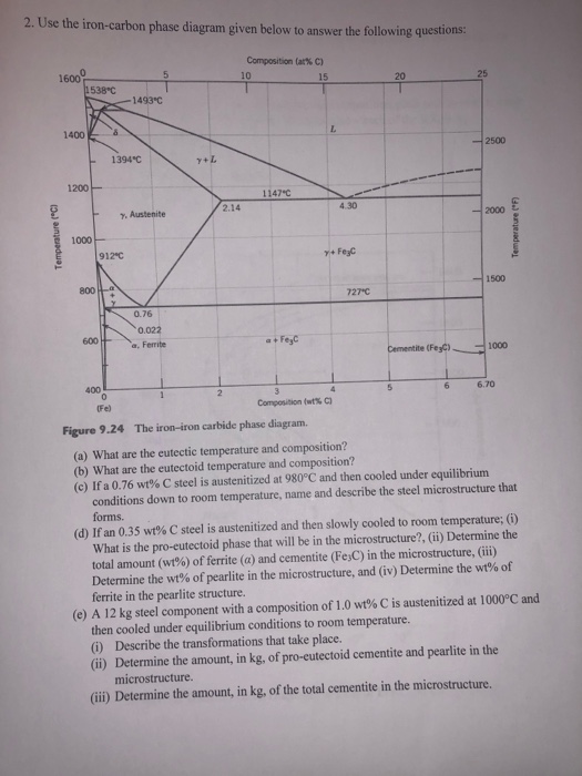
Solved 2. Use the iron-carbon phase diagram given below to ...
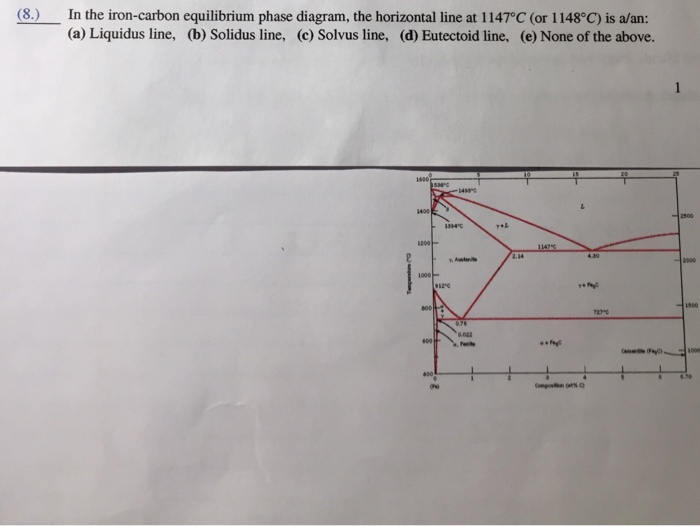
Solved (8.) In the iron-carbon equilibrium phase diagram ...
0 Response to "42 iron carbon equilibrium diagram"
Post a Comment