37 udp state transition diagram
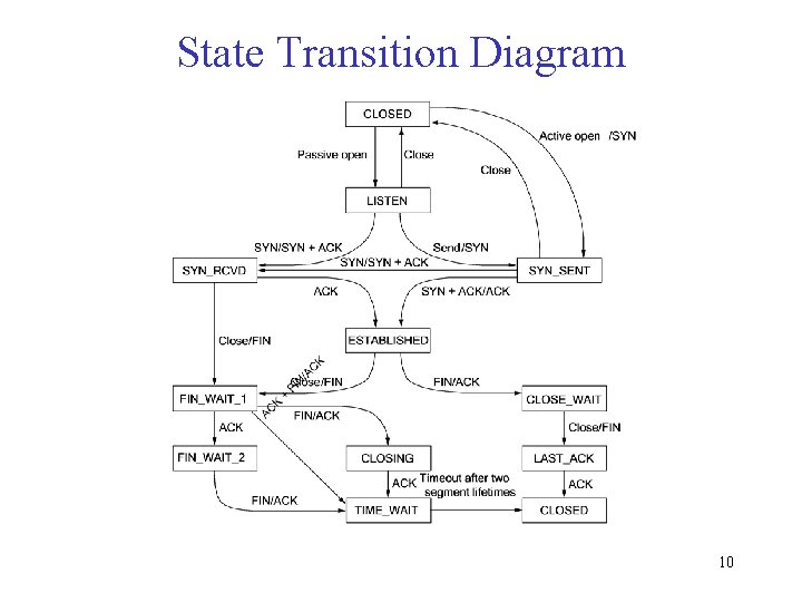
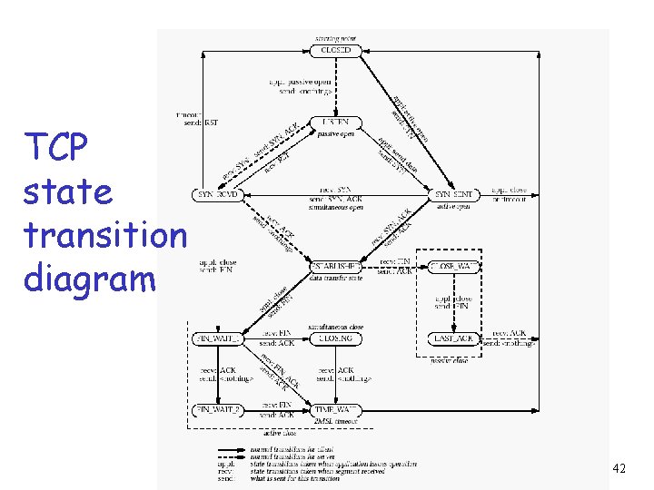
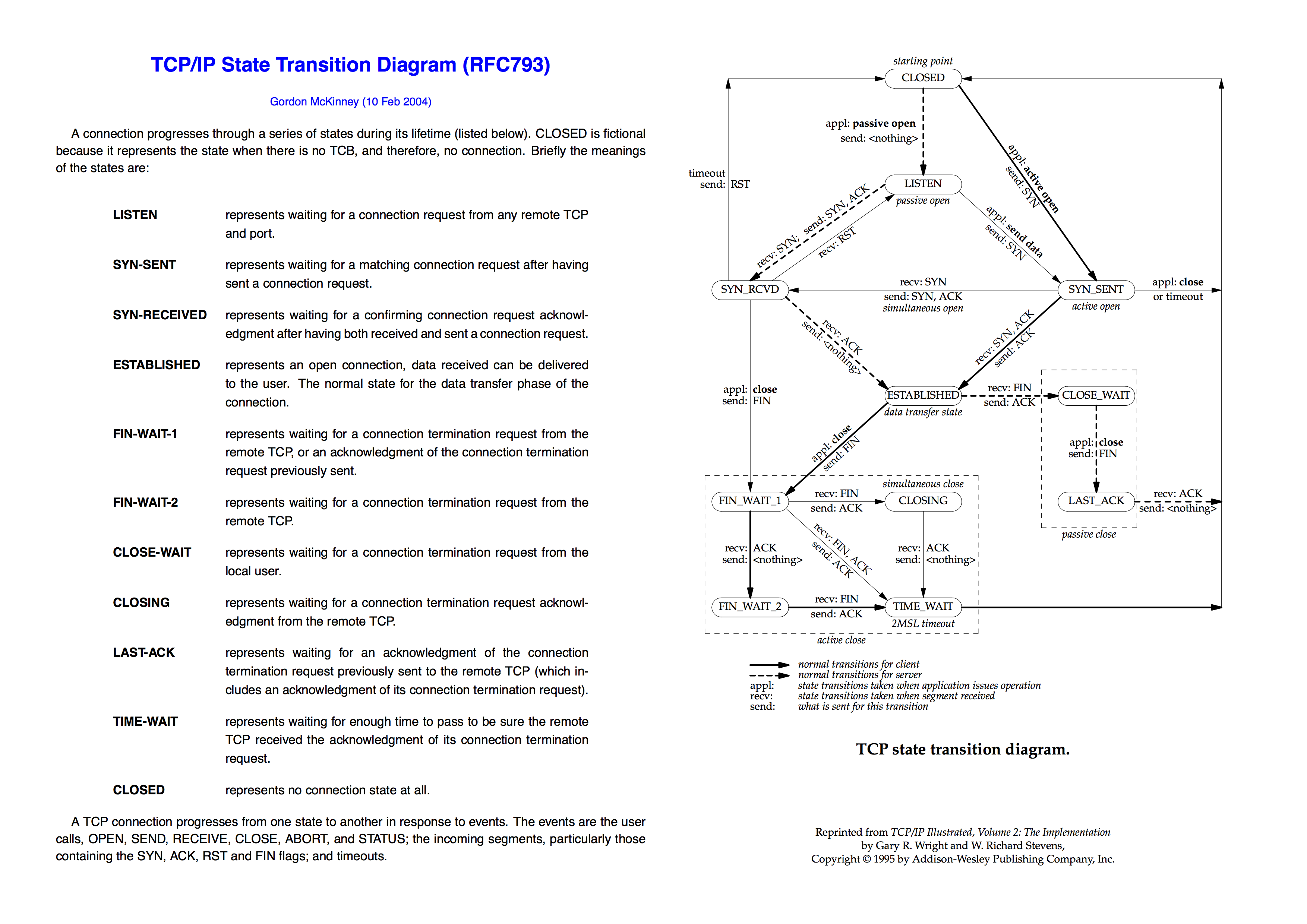
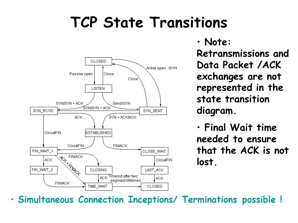
3 USER DATAGRAM PROTOCOL (UDP) ... • State Transition Diagram • Windows in TCP ... The _____ added a new state to the congestion control FSM, called the fast ... by G McKinney · 1995 · Cited by 2 — TCP/IP State Transition Diagram (RFC793). Gordon McKinney (23 Feb 2002). A connection progresses through a series of states during its lifetime.2 pagesMissing: udp | Must include: udp
User Datagram Protocol (UDP) вгдежгз ийзежгз ... Needs explicit connection establishment phase to exchange state ... State Transition Diagram ...7 pages

Udp state transition diagram
RFC 1035 Domain Implementation and Specification November 1987 in this memo, and may be datagrams. Depending on its capabilities, a name server could be a stand alone program on a dedicated machine or a process or processes on a large timeshared host. Output depends only on state Mealy FSM Moore FSM ECE 232 Verilog tutorial 26 Example 1: Sequence Detector Circuit specification: Design a circuit that outputs a 1 when three consecutive 1’s have been received as input and 0 otherwise. FSM type Moore or Mealy FSM? »Both possible »Chose Moore to simplify diagram State diagram: »State S0 ... Oct 26, 2021 · Server-side TCP responds by sending an ACK which is received by the client-side TCP. As per the TCP connection state diagram(RFC 793), in which state does the client-side TCP connection wait for the FIN from the server-side TCP? (A) LAST-ACK (B) TIME-WAIT (C) FIN-WAIT-1 (D) FIN-WAIT-2 . Explanation : (D) GATE CS 2017 (Set 1), Question 12 ...
Udp state transition diagram. Jan 25, 2022 · Backend service-based network load balancers can be used to load-balance TCP, UDP, ESP, and ICMP traffic. For architecture details, see network load balancer with a regional backend service . You can also transition an existing target pool-based network load balancer to use a backend service instead. Jun 18, 2018 · The state transition diagram of the language will be like: Here, State A represent set of all sting of length zero (0), state B represent set of all sting of length one (1), state C represent set of all sting of length two (2), state A, B, C is the final state and D is the dead state it is so because after getting any alphabet as input it will ... If all state names ending in stars are removed from Figure 8, the state diagram reduces to the standard TCP state machine (see Figure 6 of [STD-007]), with two exceptions: * STD-007 shows a direct transition from SYN-RECEIVED to FIN- WAIT-1 state when the user issues a CLOSE call. Transport Protocols: TCP and UDP. −→ end-to-end protocol ... Goal of UDP (User Datagram Protocol): ... control mechanism: −→ state transition diagram ...27 pages
Oct 26, 2021 · Server-side TCP responds by sending an ACK which is received by the client-side TCP. As per the TCP connection state diagram(RFC 793), in which state does the client-side TCP connection wait for the FIN from the server-side TCP? (A) LAST-ACK (B) TIME-WAIT (C) FIN-WAIT-1 (D) FIN-WAIT-2 . Explanation : (D) GATE CS 2017 (Set 1), Question 12 ... Output depends only on state Mealy FSM Moore FSM ECE 232 Verilog tutorial 26 Example 1: Sequence Detector Circuit specification: Design a circuit that outputs a 1 when three consecutive 1’s have been received as input and 0 otherwise. FSM type Moore or Mealy FSM? »Both possible »Chose Moore to simplify diagram State diagram: »State S0 ... RFC 1035 Domain Implementation and Specification November 1987 in this memo, and may be datagrams. Depending on its capabilities, a name server could be a stand alone program on a dedicated machine or a process or processes on a large timeshared host.
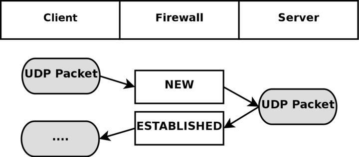
State transition diagram for HTH Upon arrival of a UDP packet ...

State transition diagram for HTH Upon arrival of a UDP packet ...

RelativityOne technical overview
Chapter 5 EndtoEnd Protocols Outline 5 1 UDP
Protocol states and transition - Stack Overflow
Transmission Control Protocol (TCP)
End to End Protocols 1 End to End
Chapter 18. TCP Connection Establishment and Termination

State transition diagram for HTH Upon arrival of a UDP packet ...

Communication Networks/TCP and UDP Protocols - Wikibooks ...

State transition diagram for ATCP at the sender [8 ...
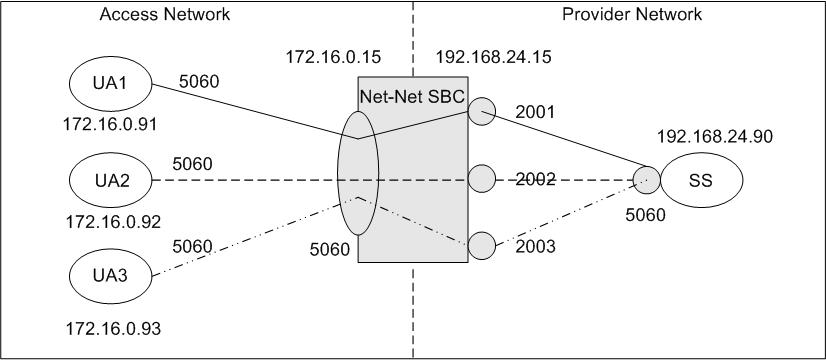
SIP Port Mapping

WebRTC 1.0: Real-Time Communication Between Browsers
250bpm
UDP connections

TCP Connection Termination - GeeksforGeeks
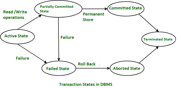
Transaction States in DBMS - GeeksforGeeks

TCP state transition diagram | TCP transition diagram
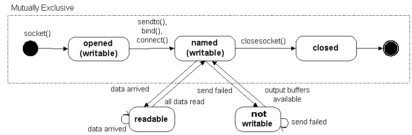
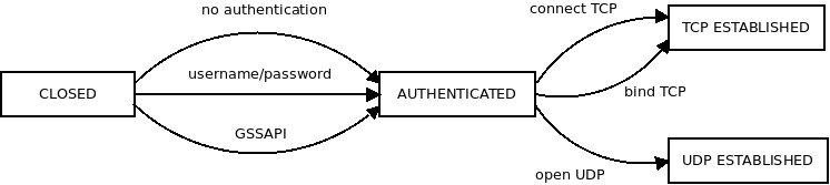
Socket States
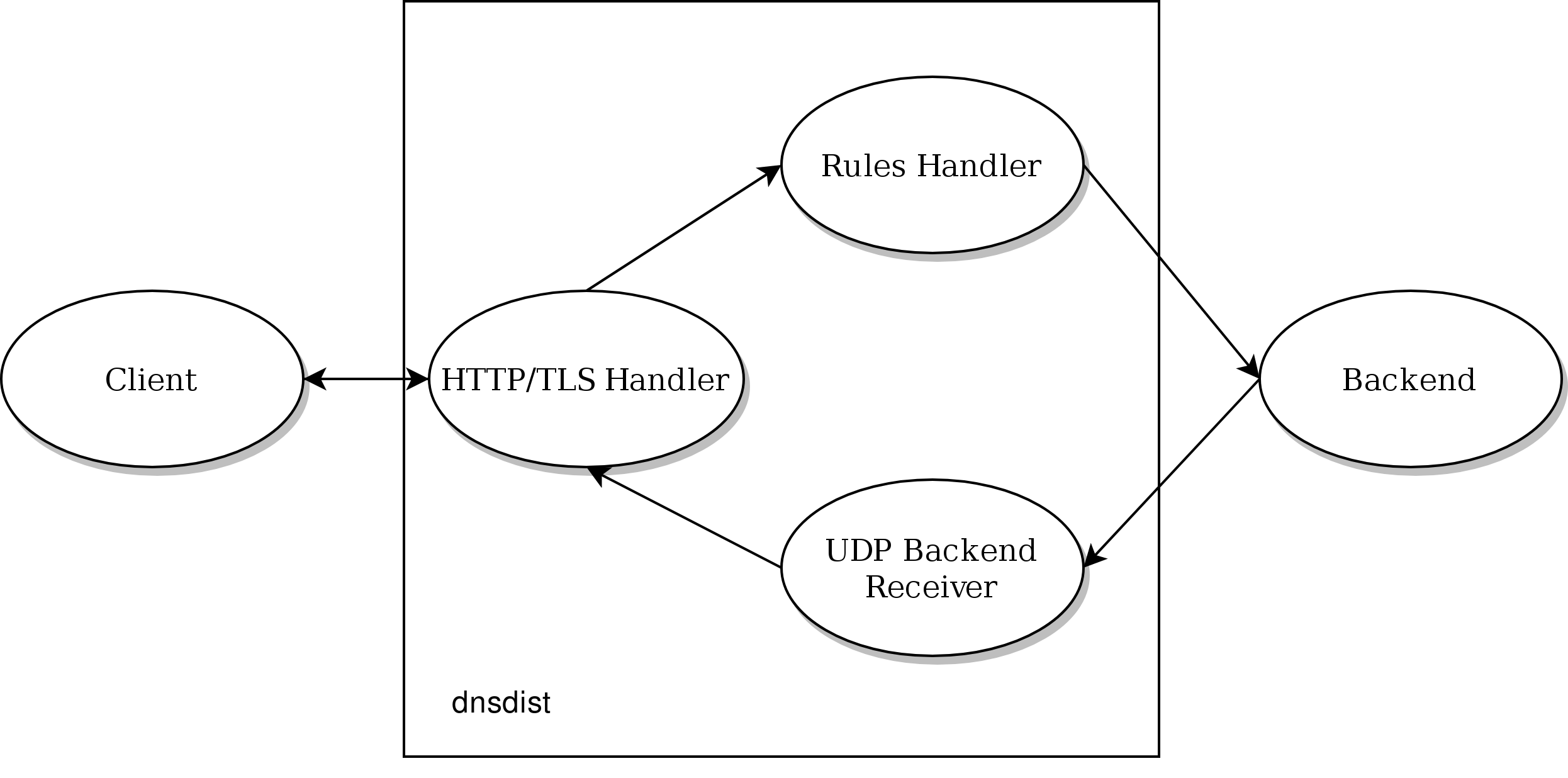
Internal Design — dnsdist documentation
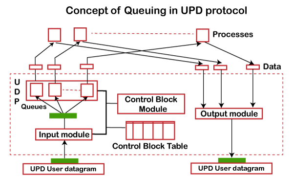
UDP Protocol | User Datagram Protocol - javatpoint
assignment1

Performance modeling and analysis of TCP and UDP flows over ...
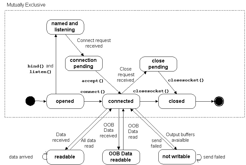
Socket States

Pseudostates - an overview | ScienceDirect Topics
Process State Transition (Programming Interfaces Guide)

3.: State-machine diagram of the UDP client end-point ...
Synthesis and biological evaluation of new inhibitors of UDP ...

16 UDP Transport — An Introduction to Computer Networks ...

Draw a state transition diagram | MCA IGNOU GROUP

UDP-sugar - an overview | ScienceDirect Topics
TCP/IP State Transition Diagram · GitHub
Transport Protocols: TCP and UDP −→ end-to-end protocol ...

tcp-state-diagram.jpg
![Chapter 6] 6.3 What Does a Packet Look Like?](https://www.cs.ait.ac.th/~on/O/oreilly/tcpip/firewall/figs/fire0606.gif)
Chapter 6] 6.3 What Does a Packet Look Like?
TCP state transition diagram.
Slide Set 13: TCP. In this set.... TCP Connection Termination ...
0 Response to "37 udp state transition diagram"
Post a Comment