42 spectrum analyzer block diagram
Spectrum Analyzer : Basics, Working, Block Diagram ... Spectrum Analyzer Block Diagram The crucial component used in the construction of the analyzer is a swept-tuned receiver. The device consists of a mixer, detector, RF type attenuator, local oscillator a LED display section. Now, let us know the operation of each component. RF Type Attenuator PDF Spectrum Analyzer 101 Plus - SBE Chapter 59 Spectrum Analyzer 101 --Spectrum Analyzer Background and Spectrum Analyzer Background and Reference Material --Block DiagramBlock Diagram --Key specifications 22 --Controls and SettingsControls and Settings --HandsHands--on measurementson measurements——Analog and Analog and Digital signals --Hints and KinksHints and ...
Spectrum Analyzers - Tutorialspoint The following figure shows the block diagram of filter bank spectrum analyzer. The working of filter bank spectrum analyzer is mentioned below. It has a set of band pass filters and each one is designed for allowing a specific band of frequencies. The output of each band pass filter is given to a corresponding detector.

Spectrum analyzer block diagram
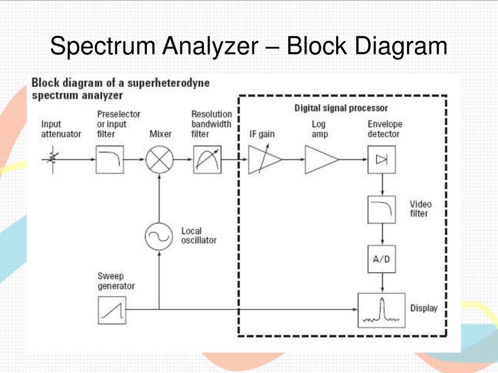
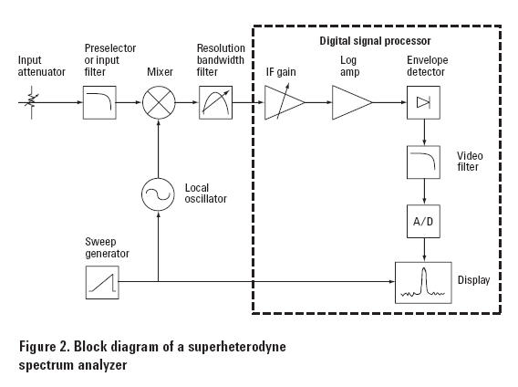
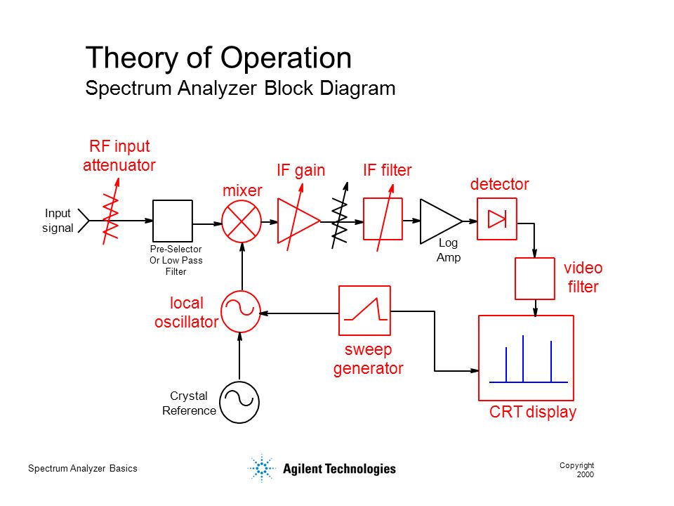
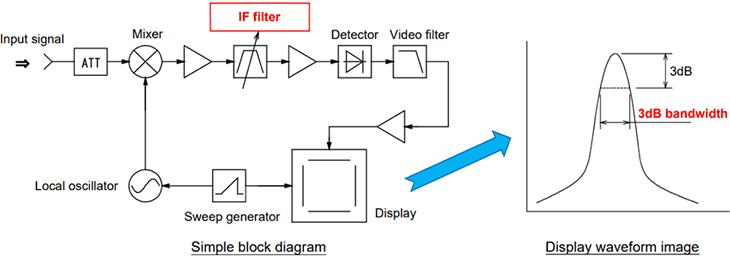
What is Spectrum Analyzer? Block Diagram, Working and ... Block Diagram Working Applications What is Spectrum Analyzer? A spectrum analyzer is considered as a device that is used for the analysis of the amplitude of the signal with respect to frequency. So, an input waveform provided to a spectrum analyzer is analyzed on the basis of varying frequency. Agilent Technologies - Spectrum Analyzer ... - Keysight The spectrum analyzer, like an oscilloscope, is a basic tool used for observing signals. Where the oscilloscope provides a window into the time domain, the spectrum analyzer provides a window into the frequency domain, as depicted in Figure 1. Figure 2 depicts a simplified block diagram of a swept-tuned superheterodyne spectrum analyzer. spectrum analyzers ppt - SlideShare Spectrum Analyzer Block Diagram 15. Major blocks in a spectrum analyzer are:- 1] RF input attenuator, 2] Mixer, 3] IF (Intermediate Frequency) gain, 4] IF filter, 5] Detector, 6] Video filter, 7] Local oscillator, 8] Sweep generator, and 9] CRT display. 16.
Spectrum analyzer block diagram. PDF Spectrum Analyzers Field User Guide Block Diagram Description Spectrum analyzer users need to understand major analyzer functional blocks. While most of the choices described here are made automatically, manual selections are possible and can be helpful. The DC block prevents DC voltage from entering the instrument, and allows measuring lines with DC power. Understanding and Eliminating 1/f Noise - Analog Devices ADA4522 architecture block diagram. Referring to the ADA4522-2 architecture block diagram shown in Figure 4, the input signal is modulated to the chopping frequency at the CHOP IN stage. At the CHOP OUT stage, the input signal is synchronously demodulated back to its original frequency and simultaneously the offset and 1/f noise of the ... PDF Experiment 1 Spectrum Analyzer - HIT Block diagram of a Spectrum Analyzer-Draw a block diagram of a spectrum analyzer, and explain brie⁄y each of the following blocks (Attenuator,ampli-er,LPF, IF -lter, envelope detector, video -lter, display, LO, Ramp generator). 1.3.4 Problem-4 Shape factor of a Gaussian -lter-The voltage of a gaussian shape -lter is given by V (f ... Movies Archives - Hollywood.com Click to get the latest Movies content. Sign up for your weekly dose of feel-good entertainment and movie content!
Spectrum Analyzer 0...1750MHz - Association of Radio ... Fig.1 - Spectrum-analyzer block diagram. As already mentioned in [1] and [2], the described spectrum analyzer is a triple-conversion receiver with the corresponding IFs around 2.1GHz, 70MHz and 10MHz. Since both the first LO and the second LO are VCOs, the first IF may be made variable. PDF Superheterodyne Spectrum Analyzer and Spectrum Analysis a spectrum analyzer. 2.2 Spectrum Analyzer Block Diagram and Theory of Operation The main components of Spectrum Analyzer are an RF input attenuator, input am-plifier, mixer, IF amplifier, IF filter, envelope detector, video filter, CRT display, LO, ramp generator(see Fig - 2 ). Lets describe each component individually Digital Communication System Block Diagram with Explanation ... Sep 22, 2021 · As illustrated in the block diagram, an analog signal may always be transformed into a digital signal by combining three fundamental operations: sampling, quantizing and encoding. Only sample values of the analog signal at regularly spaced discrete-time instants are maintained during the sampling procedure. Spectrum Analysis Basics - Part 2: What's in a spectrum ... Figure 2: A diagram of an RF attenuator, the first block of a spectrum analyzer. An RF attenuator, shown in Figure 2, ensures the signal enters the mixer at an optimum level. If a signal is too high in amplitude, it may overload the mixer, leading to distortion. This component protects the analyzer from damage.
ECE 489 - Communications System Laboratory: Lab 5 16 QAM ... The Transmitter consists of a Bit generation block and a modulator block. The channel adds artificial distortions (frequency, phase, DC level, and delay). Double click on the channel subsystem and examine the components inside. The receiver consists of multiple subsystems in order to correct for the distortions added through the channel. courses:ec330_2009:spectrumanalyzer [Integrated Circuits ... The block diagram of the spectrum analyzer is shown in the above figure. Each block is described briefly below. For a more detailed description of the spectrum analyzer, see the references at the end of the page. PDF SPECTRUM ANALYZER - Bharath Institute of Higher Education ... A block diagram of an audio spectrum analyzer. SPECTRUM ANALYZERS •The real-time, or multichannel. analyzer is basically a set of stagger-tuned bandpass filters connected through an electronic scan switch to a CRT. The composite amplitude of the signal within each filters bandwidth is displayed as a ... Superheterodyne Spectrum Analyzer ... - Electronics Notes Superheterodyne or swept frequency spectrum analyzer block diagram The frequency of the local oscillator governs the frequency of the signal that will pass through the intermediate frequency filter. This is swept in frequency (linearly increasing in frequency) so that it covers the required band.
Block diagram of the correlation spectrum analyzer ...
PDF Understanding Key Real-Time Spectrum Analyzer ... Figure 3. Block diagram of simplified vector signal analyzer and signal processing flow. Nearly all modern spectrum analyzers combine the features of both the traditional swept spectrum analyzer and a vector signal analyzer. If the span is greater than the FFT analysis bandwidth, the LO will be stepped

TIDA-00929 reference design | TI.com
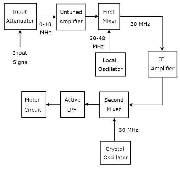
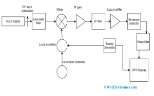
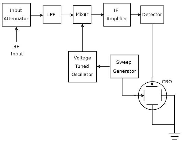
Spectrum Analyzer : Working Principle, Classfication & Its ... Block Diagram The block diagram of the spectrum analyzer is shown above. It consists of an input attenuator, which attenuates the input radio frequency signal. The attenuated signal is fed to a low pass filter to eliminate the ripple content. The filtered signal is mixed with a voltage tuned oscillator, and fed to an amplifier.

Vector signal analyzer - Wikipedia
PDF Real-Time Spectrum Analyzer Fundamentals Figures 1-2 a, b, c. Simplified Block Diagram of Swept Spectrum Analyzer (a), Vector Signal Analyzer (b), and Real-Time Spectrum Analyzer (c). a) Swept Tuned Spectrum Analyzer (SA) b) Vector Signal Analyzer (VSA) c) Real-Time Spectrum Analyzer (RSA6100 Series + Option 110) Attenuator Attenuator Low-Pass Low-Pass RF Downconverter Real-Time Digital
Block Diagram Of The Spectrum Analyzer Audio Spectrum ...
PDF Keysight MXA Signal Analyzer Option BBA: Analog Baseband ... The Keysight MXA signal analyzer features state-of-the-art signal and spectrum analysis, and offers the highest mid-range analyzer performance in the industry today. ... MXA signal analyzer block diagram (RF and analog BB) 1. If 25 MHz bandwidth is sufficient for both RF and baseband, order Option B25 (not S40) with Option BBA. Refer to the ...
courses:ec330_2013:spectrumanalyzer [Integrated Circuits and ...
Spectrum Analyzer - MathWorks Add a Spectrum Analyzer block to your block diagram. If your model uses a variable-step solver, also add a Rate Transition block and connect it to the input of the Spectrum Analyzer, setting the Output port sample time to the sample time you wish the Spectrum Analyzer to use.

Homebrew spectrum analyser
PDF Spectrum Analysis Back to Basics - Institute of Electrical ... seems confusing now - as we discuss the block diagram, the concept will become clearer. We will first go into more detail as to how the swept spectrum analyzer works. Then we will compare that architecture to the architecture of a modern FFT analyzer.
Spectrum Analyzer 0...1750MHz
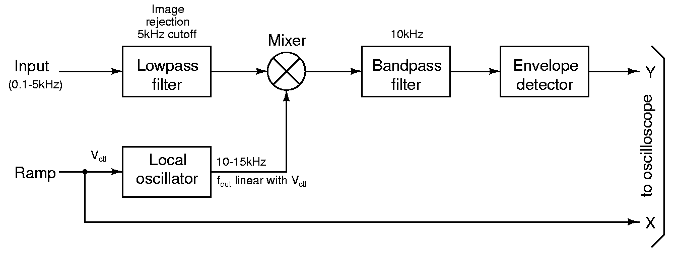
Spectrum Analyzer with Block Diagram - Electronics and ... The block diagram of a spectrum analyzer of swept frequency type is shown in Figure. It can be seen from the block diagram that the horizontal deflection is obtained from a saw tooth wave generator. The output of the saw tooth wave controls the frequency of the Voltage Controlled Oscillator (also called the voltage tuned oscillator).

Spectrum Analyzer Block Diagram | Parallel Filter Bank ...
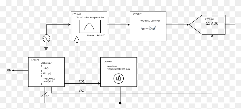
Block diagram for spectrum analyzer. | Download Scientific ... Block diagram for spectrum analyzer. Source publication A Technique to Accurately Predict EMI Noise Spectrum in Wide Frequency Ranges Based on the Principles of Spectrum Analyzers

EA4EOZ, an amateur radio electronic enthusiast: Repairing an ...
Detection and Measurement of Radar Signals: A Tutorial the spectrum analyzer input is +10 dBm with 50 dB of internal spectrum analyzer attenuation invoked at the front end, then the amount of attenuation that needs to be inserted between the coupler output and the spectrum analyzer input is (90–20–50–10) = 10 dB.

Obtain Measurements Data Programmatically for Spectrum ...
RF1100 - Effective Spectrum Analyzer Measurements 2.1 Introduction to Spectrum Analysis 2.2 Basic Spectrum Analyzer Block Diagram 2.3 Microwave Spectrum Analyzer 2.4 Harmonic Mixer Responses 2.5 Front-End Filtering 2.6 Preselector Response 2.7 Microwave and Low Band Architecture 2.8 Tracking Generator Architecture 2.9 Supporting Notes 2.10 Module Quiz
A 2.5-GHz Tracking Generator for the HP 8566A/B Spectrum Analyzer
FFT Spectrum Analyzer: Fast Fourier ... - Electronics Notes The FFT spectrum analyzer can be considered to comprise of a number of circuit different blocks: FFT Spectrum Analyser Block Diagram. Analogue front end attenuators / gain: The test instrument requires stages at the input of the FFT analyser to ensure that the signal is at the required level for the analogue to digital conversion. These stages ...
Wave Analyzers
PDF MAINTENANCE MANUAL MS2711 Hand Held Spectrum Analyzer The MS2711 Spectrum Analyzer (Figure 1) is a syn- thesizer-based hand held spectrum analyzer that provides quick and accurate signal results. Measure- ments can be easily made using the main instrument functions: frequency, span, amplitude and band- width. A simplified block diagram is provided in Fig- ure 2. 3. PERFORMANCE VERIFICATION PROCEDURES
Block Diagram Of The Spectrum Analyzer - Audio Spectrum ...
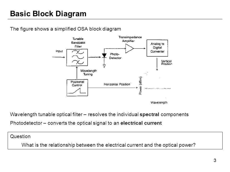
Optical Spectrum Analyzer function | OSA Application Note The figure-2 depicts simple block diagram of Optical Spectrum Analyzer . Let us understand functions of each of the modules of OSA. • Incoming optical signal to be measured is passed through wavelength tunable filter. This optical filter resolves different spectral components individually. • Photodetector converts optical signal into ...

Block diagram for a digital cross-correlation spectrum ...
EEC2: Block Diagram: Spectrum Analyzer - YouTube This video describes the architecture and functionality of the Spectrum Analyzer.
SPECTRUM ANALYZER
Spectrum Analyzer block Diagram, Basics and Working in ... In this video, i have explained Spectrum Analyzer block Diagram, Basics and Working with following outlines.1. Spectrum Analyzer basics2. Spectrum Analyzer B...
PPT - Spectrum Analyzers And Network Analyzers The Whats ...
Understanding Spread Spectrum for Communications - NI Jan 05, 2022 · The block diagram of the DSSS communication system for QPSK is presented in Figure 6. Notice that the PN sequence is introduced here to both in-phase (I) and quadrature (Q) components. Figure 6: Block diagram of the spread spectrum QPSK modulator The sequence should be long enough (with respect to the message signal) to have the noise-like ...
Agilent Technologies - 8 Hints for Spectrum Analysis
spectrum analyzers ppt - SlideShare Spectrum Analyzer Block Diagram 15. Major blocks in a spectrum analyzer are:- 1] RF input attenuator, 2] Mixer, 3] IF (Intermediate Frequency) gain, 4] IF filter, 5] Detector, 6] Video filter, 7] Local oscillator, 8] Sweep generator, and 9] CRT display. 16.
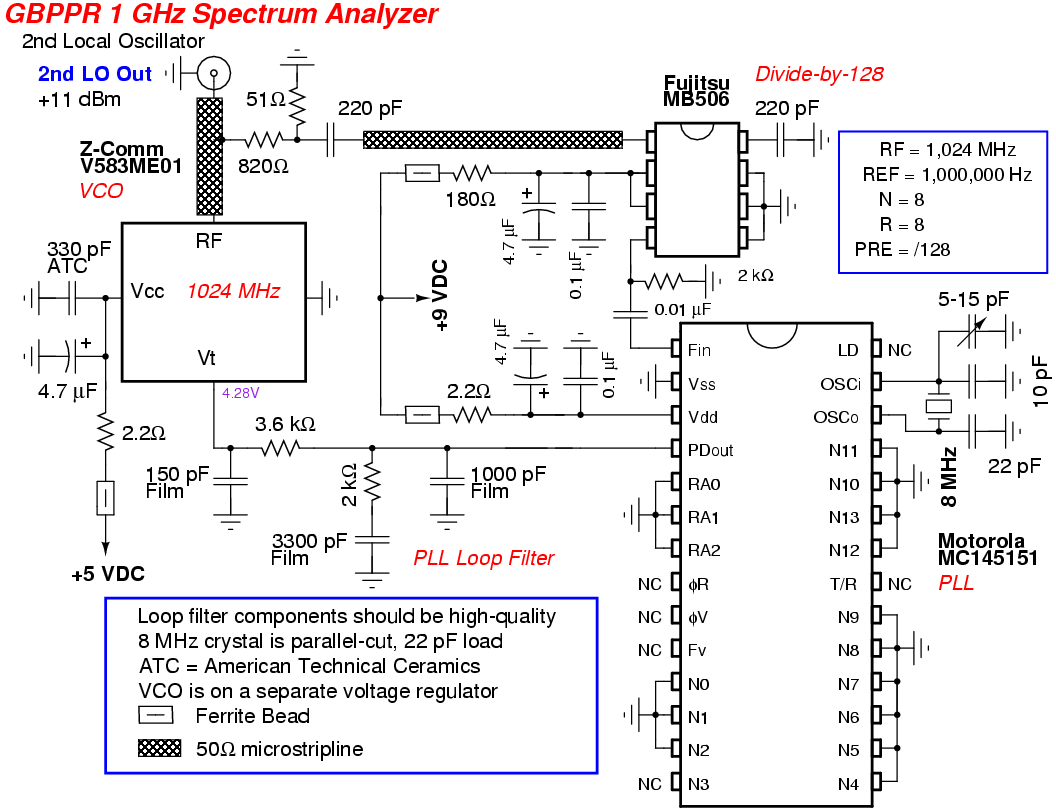
GBPPR 1 GHz RF Spectrum Analyzer
Agilent Technologies - Spectrum Analyzer ... - Keysight The spectrum analyzer, like an oscilloscope, is a basic tool used for observing signals. Where the oscilloscope provides a window into the time domain, the spectrum analyzer provides a window into the frequency domain, as depicted in Figure 1. Figure 2 depicts a simplified block diagram of a swept-tuned superheterodyne spectrum analyzer.
A Study on BASICS OF A SPECTRUM ANALYZER
What is Spectrum Analyzer? Block Diagram, Working and ... Block Diagram Working Applications What is Spectrum Analyzer? A spectrum analyzer is considered as a device that is used for the analysis of the amplitude of the signal with respect to frequency. So, an input waveform provided to a spectrum analyzer is analyzed on the basis of varying frequency.
Spectrum Analyzer Basics Copyright 2000 Agenda Overview: What ...
Achieving Amplitude Accuracy in Modern Spectrum Analyzers
Block Diagram Of The Spectrum Analyzer - Audio Spectrum ...
Spectrum Analyzer : Basics, Working, Block Diagram ...
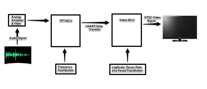
ECE 4760 Audio Spectrum Analyzer

Optical Spectrum Analyzer function | OSA Application Note
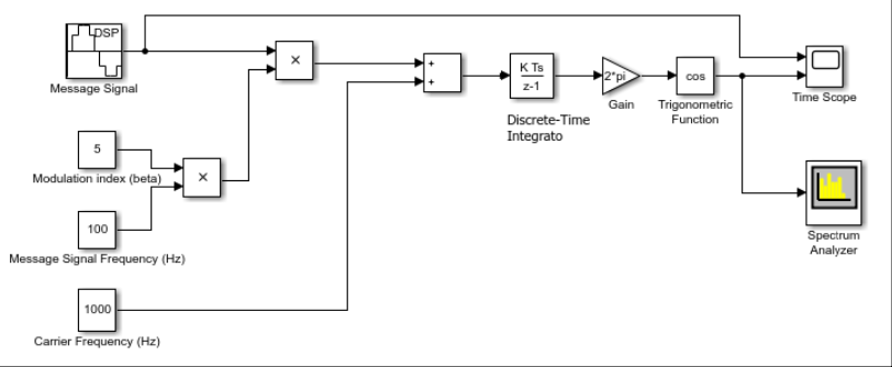
Load S2_FM1.slx, remove the Spectrum Analyzer block | Chegg.com

Block Diagram Of The Spectrum Analyzer - Audio Spectrum ...
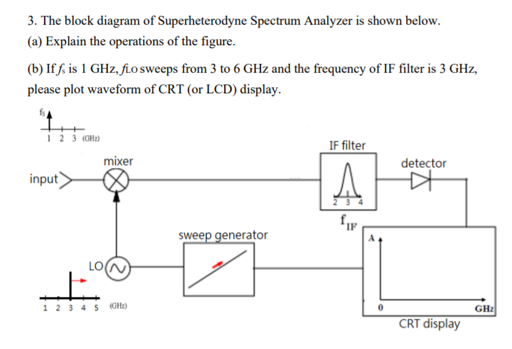
Solved 3. The block diagram of Superheterodyne Spectrum ...

Audio Spectrum Analyzer
Measurements 2: Network Analysis
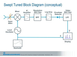
Spectrum Analyzer Fundamentals/Advanced Spectrum Analysis

Spectrum analyzers today and tomorrow: part 1 towards ...
![Solved] Figure P5.53 shows the block diagram of a possible ...](https://s3.amazonaws.com/si.question.images/images/question_images/1610/6/1/7/672600013488f9221610617671957.jpg)
Solved] Figure P5.53 shows the block diagram of a possible ...
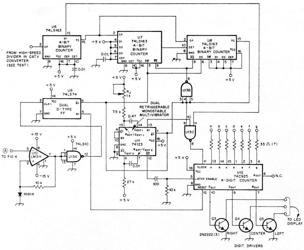
An inexpensive spectrum analyzer for the radio amateur
Spectrum Analyzers

Signal analyzer - Wikipedia

GBPPR 1 GHz RF Spectrum Analyzer | Spectrum analyzer ...
Spectrum Analyzer Basics (2) About RBW (Resolution Bandwidth ...

MSA Tracking Generator

Spectrum Analyzer with Block Diagram - Electronics and ...
Chapter Three – Optical Spectrum Analysis - ppt download
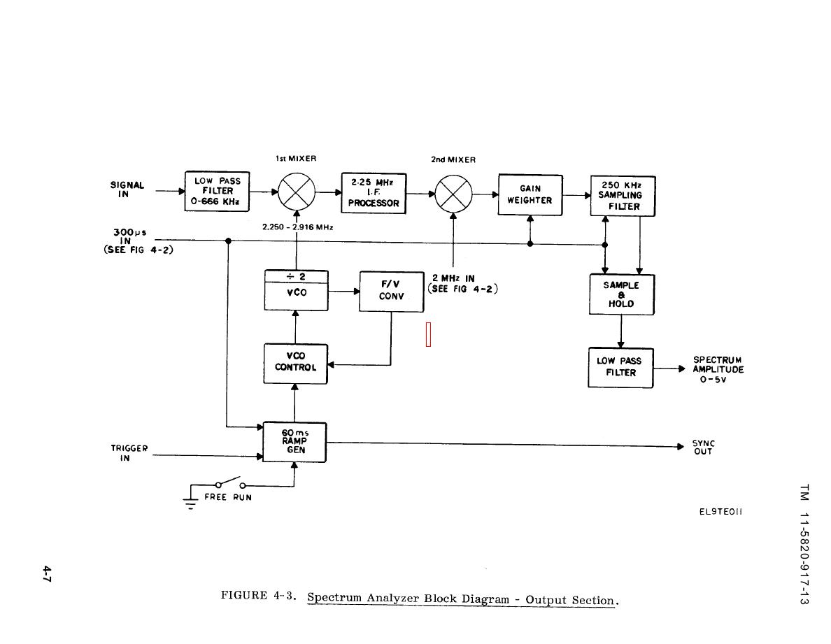
Figure 4-3. Spectrum Analyzer Block Diagram - Output Section
0 Response to "42 spectrum analyzer block diagram"
Post a Comment