38 plc ladder diagram for traffic light
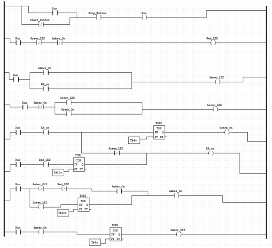
PLC Ladder Logic Diagram for Traffic Signal. - Instructables PLC Ladder Logic Diagram for Traffic Signal. By muneeb4889 in Circuits Software. 4,086. 2. Introduction: PLC Ladder Logic Diagram for Traffic Signal. By muneeb4889 muneeb aslam. More by the author: About: i am an electronics engineer and a short story writter for my strories visit :-muneebzargar.blogspot.in More About muneeb4889 ». Traffic Light Control using PLC Ladder Logic | Traffic ... Conclusion: The above-explained 3 ways traffic light control using PLC is for example only. It may vary from real-time. We can use this example program to understand the working of timers and comparator block function in AB PLC. If you liked this article, then please subscribe to our YouTube Channel for PLC and SCADA video tutorials.
PDF Traffic Light Ladder Logic Diagram Using Sequence Plc Ladder Logic Diagram For Traffic Light ladder diagram one way traffic light Signal Operations - University of Idaho-Moscow, Boise, Coeur d. I need to write a simple ladder diagram to control a traffic light. This had to be done using one plc. simulator that works on ladder logic. There was no way i would. A Traffic Light State Diagram.

Plc ladder diagram for traffic light
Traffic light using plc - SlideShare HISTORY:- • Traffic lights are signaling devices positioned at road intersections, pedestriancrossings are today used in almost every city of the world. • On December 10, 1868, the first traffic lights were installed outside the British houses of parliament in London,bythe railway engineer J.P. Knight. Three way Traffic Light Control using PLC - Automation ... Design ladder logic for Three way traffic light control system using Programmable Logic Controller PLC programming. The traffic light is one of the classic examples in PLC ladder logic.. We can take three directions (North, South, west, and east) with three outputs (Green, Red, and Yellow) lamp as output. PDF Experiment 2 Traffic Light Control System for An ... Understanding the programmable logic controller and its peripherals. Programming the PLC with the STEP 7 software. Applying the PLC to control the operation of a demand-actuated traffic light system in an intersection. Equipments: Table 1. List of Equipments 728 740 Traffic Light Crossing 730 800 PLC Basic Unit
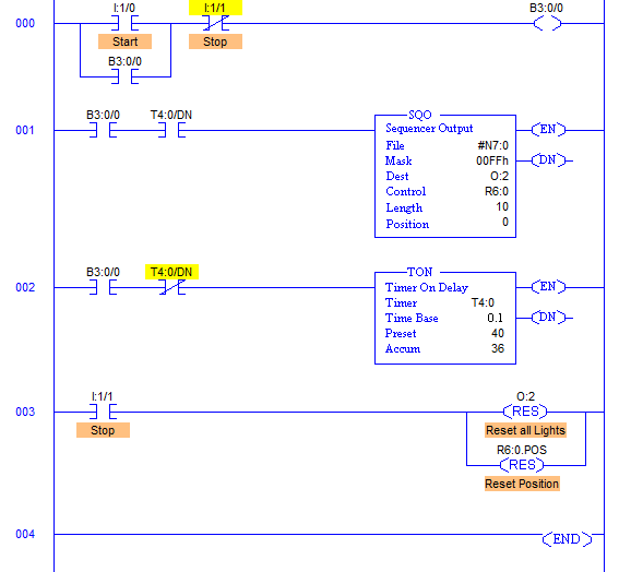
Plc ladder diagram for traffic light. PLC Ladder Logic Programming Examples with detailed ... Three lights RED, YELLOW, and GREEN are connected with outputs Y0, Y1, and Y2. One switch is connected with X0 to activate and deactivate the traffic control system. Now let's have a look at the ladder logic diagram of the PLC based traffic control system. PLC based Traffic Light Control System Ladder Logic Diagram: Traffic Light Ladder Logic Diagram Using Sequence Bookmark File PDF Traffic Light Ladder Logic Diagram Using Sequence Tony Fischer-Cripps is a Project Leader in the Division of Telecommunications and Industrial Physics of the CSIRO (Commonwealth Scientific & Industrial Research Organisation), Australia. He was previously lecturer, University of Technology, Sydney (UTS), Australia, and has also "[Help] PLC ladder diagram for traffic light (4way)" Steve Bailey - (85 posts): Feb-06-02, 09:29 AM (EST) 3. "RE: [Help] PLC ladder diagram for traffic light (4way)" You won't make any friends among the drivers on Avenue A and Boulevard B if you make them wait for a full minute for a single vehicle to enter from Causeway C or D Drive. PLC Ladder Diagrams - Traffic Lights | Automation ... Nov 3, 2001. #6. One point not raised is the requirement of redundancy in regards to the safety of a traffic light system. There is available plc's for this purpose. If it is not for use in a real situation and just a plc project for learning purposes then the AB plc offers a sequencer which is ideal for this prupose. D.
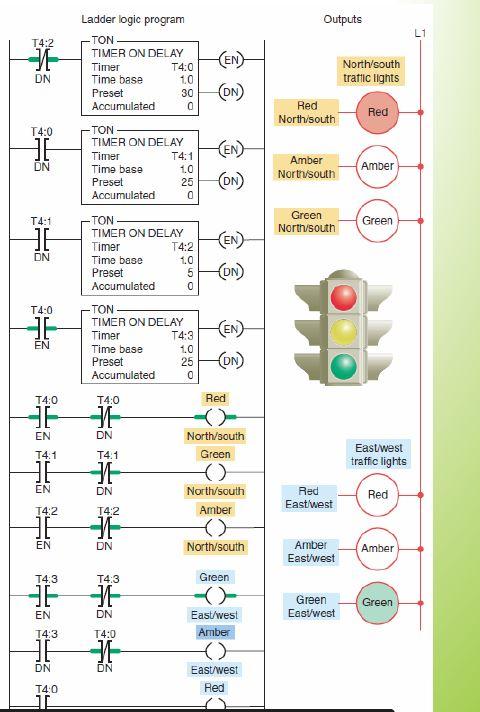
Control Of Traffic Light Ladder Logic Diagram | Ladder ... Dec 1, 2019 - Control Of Traffic Light Ladder Logic Diagram. Dec 1, 2019 - Control Of Traffic Light Ladder Logic Diagram. Pinterest. Today. Explore. ... Introduction to PLC ladder logic programming training video. This educational video is an introduction to what ladder logic is and how it works. (Part 1 of 2... PLC Program for Traffic Light Control - PLC Tutorial Point Control Purpose: Enabling the traffic lights to work by Start button X0 and to stop by Stop button X1. Setting the time of red light in East-West direction as 60 sec and North-South direction with a heavier traffic as 30 sec. yellow light" in North-south direction, and vice versa. 5 sec for the crossing cars and pedestrians to pass safely. PDF Traffic Light Ladder Logic Diagram Allen Bradley Traffic Light Ladder Logic Diagram Allen Bradley PLC Program to Drive Motor in Forward and Reverse Direction. ALLEN BRADLEY POWERFLEX 525 USER MANUAL Pdf Download. catalog 2017 2018 Farmingdale State College. BibMe Free Bibliography amp Citation Maker MLA APA. the of and to a in that is was he for it with as his on be. (PDF) Traffic light control system using S7 300 PLC ... Use of PENCIL IS NOT ALLOWED EXPERIMENT 4: TRAFFIC LIGHT CONTROL SYSTEM FOR AN INTERSECTION USING S7-300 PLC STUDENT NO STUDENT NAME SIGNATURE DATE 1 2 INSTRUCTOR APPROVAL 3 4 Please include flowchart of your program in here indicating inputs and outputs (ladder diagram code must be included in your report).
FOUR WAY TRAFFIC CONTROL BY USING PLC - Technical Hub There are 5 programming languages which are used for the programming a PLC. The list is as follows: 1. Functional block diagram. 2. Ladder diagram. 3. Structure text. 4. Instruction list. 5. Sequential flow chart. Out of these five languages, Ladder diagrams is most widely used program because it is simple and easier to understand among all ... PDF Chapter 2: Basic Ladder Logic Programming Ladder Logic Diagram Example 1 Computer Aided Manufacturing TECH 4/53350 27 Task: Draw a ladder diagram that will cause the output, pilot light PL2, to be on when selector switch SS2 is closed, push button PB4 is closed and limit switch LS3 is open. (Note: no I/O addresses yet.) Thought Process ladder diagram one way traffic light - MathewSpain's blog Ladder diagram consists of one vertical line found on the left hand. conditions determines when and in what way. Traffic Light with PLC; Weighing Machine Using PLC Here's one way of making sure the traffic light is always "green": a team of researchers at the University of Nebraska-Lincoln is working on a three-year green. TheLearningPit mitsubishi plc traffic light ladder diagram - PLC Controller DVP20SX211T DATEL Plc controller, low cost plc controller,20 point,8DI/6DO NPN Transistor. DVP24ES200R, DVP24ES200T DATEL Plc controller, 16DI/8DO ... Fx1s and op320 communication line connection diagram. G6F-AD2A Authentic original LS(LG) PLC CONTROLLER. G6I-D24A Authentic original LS(LG) PLC CONTROLLER Input module. G6Q-TR2A Authentic ...
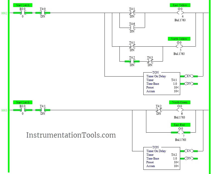
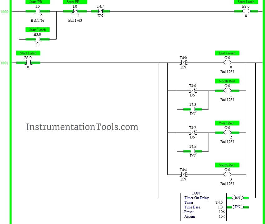
PLC based 4 Way Traffic Light Control System ... The above explained 4 ways traffic light control using PLC is for example only. It may vary from real time. We can use this example program to understand the working of timers and Interlocking function in AB PLC. Author : Hema Sundaresan. If you liked this article, then please subscribe to our YouTube Channel for PLC and SCADA video tutorials.
PDF Plc ladder diagram for traffic light control using timers pdf Plc ladder diagram for traffic light control using timers pdf. Do-More, Do-More Designer, PLC, PLC Basics, PLC Learn May 10, 2015 garrys Leave a comment In part 1 we examined the writing of PLC programs to control a traffic light using discrete bits and then using the punctual sequence using the indirect address.
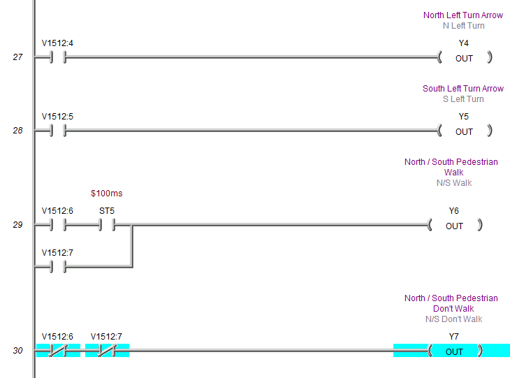
Ladder Logic Examples and PLC Programming Examples Traffic Light Ladder Logic Diagram. One of the most used applications for a PLC is the traffic lights. At many schools, universities and even companies you will get the challenge to make a traffic light ladder logic diagram. The traffic light PLC program is a combination of timers to control which lights are turned on and for how long time.
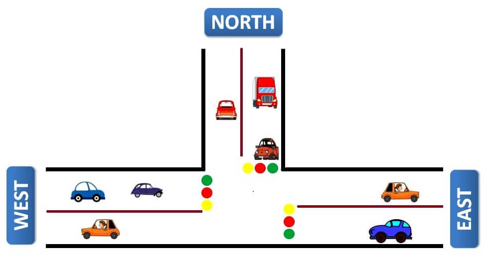
Traffic Light Control using PLC Ladder Logic Programming The traffic light is one of the classic examples in PLC ladder logic. We can take four directions (North, South, west, and east) with three output lamps (Green, Red, and Yellow). You can build your own concept for making logic for this example. Follow below tabular column - Logic for the four way traffic light List of Inputs and Outputs
PDF Plc Ladder Logic Diagram For Traffic Light Traffic Light That Are Used To Program A PLC Ladder Diagram Traffic Light Logic On PLC Using Ladder' 'plc ladder logic diagram for traffic light softys de may 3rd, 2018 - read and download plc ladder logic diagram for traffic light free ebooks in pdf format 1997 international 4700 manual 2010 jetta sportwagen tdi owners manual holden'
PLC Ladder logic example for beginners: Four-Way traffic ... Let's discuss the four-way traffic light control and solution based on PLC controller using ladder logic program. For this purpose, we have used Siemens PLC software TIA PORTAL V15 for developing the ladder logic program. This is one of the common examples for PLC programming beginners. FOUR-WAY TRAFFIC LIGHT CONTROL DIAGRAM
PDF CHAPTER 5 CONCLUSION 5.1 Summary - Universiti Malaysia Perlis The PLC program (ladder logic diagram) for implement the three mode of traffic light operation; Normal Mode, emergency Mode and Night Mode, have been designed completely and can be operated effectively together with the model of emergency sensor (switch) for the Emergency mode and the IR sensor circuit
Traffic Signal PLC Ladder Programming tutorial - YouTube #TrafficSignal #TrafficLight #PlcProgramming #plc #plctutorial #plcbasics #ladderlogic #ladderdiagram #programmablelogiccontrollerTutorial for Traffic Signal...
PLC Training 52 - Traffic Light Control using PLC Ladder ... Write a PLC program for two-way traffic light control using ladder logic programming.4 Way Traffic Light Control Logichttps://instrumentationtools.com/plc-ba...
Traffic Light Plc Ladder Logic Diagram - Wiring Diagram ... Solved Make A Plc Ladder Diagram Program For Traffic Ligh. Plc Program To Control Traffic Lights Sanfoundry. Water Heater Ladder Diagram Siemens Plc Ladder Logic Examples. Logixsim Plclogix. Plc Program Traffic Light Youtube. 1582904514000000.
Plc Ladder Logic Diagram For Traffic Light ... Diagram A Ladder Logic Full Version Hd Quality Lovediagram Andreapendibene It. Three Way Traffic Light Control Using Plc Automation Community. Traffic Light Automation Control Program Designed By A Student Scientific Diagram. Plc Based 4 Way Traffic Light Control System Instrumentationtools.
Smart Traffic Control System using PLC Programming and LD ... Today, we are studying the Traffic Control System using programmable logic controller (PLC) programming based on Ladder Diagram. One of the best use of PLC programming is to control, start and stop the signals in the system. We saw different PLC software brands. For most of the project work, we use the Allen Bradley (AB) and Siemens PLC brand ...
PDF Experiment 2 Traffic Light Control System for An ... Understanding the programmable logic controller and its peripherals. Programming the PLC with the STEP 7 software. Applying the PLC to control the operation of a demand-actuated traffic light system in an intersection. Equipments: Table 1. List of Equipments 728 740 Traffic Light Crossing 730 800 PLC Basic Unit
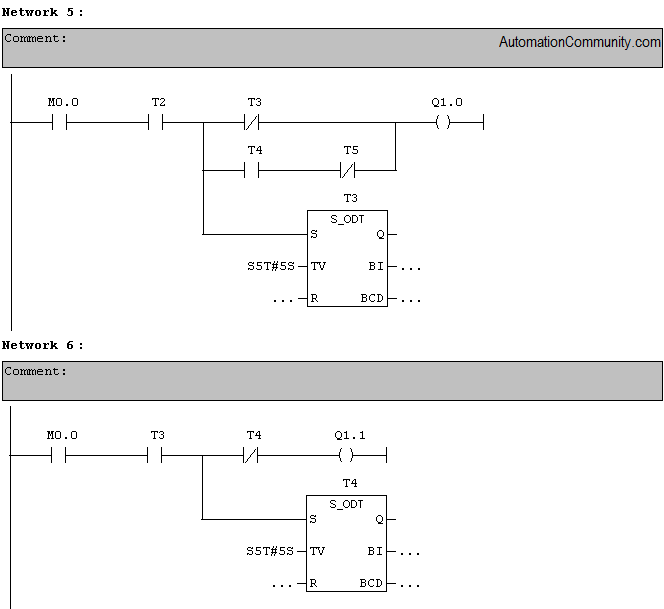
Three way Traffic Light Control using PLC - Automation ... Design ladder logic for Three way traffic light control system using Programmable Logic Controller PLC programming. The traffic light is one of the classic examples in PLC ladder logic.. We can take three directions (North, South, west, and east) with three outputs (Green, Red, and Yellow) lamp as output.
Traffic light using plc - SlideShare HISTORY:- • Traffic lights are signaling devices positioned at road intersections, pedestriancrossings are today used in almost every city of the world. • On December 10, 1868, the first traffic lights were installed outside the British houses of parliament in London,bythe railway engineer J.P. Knight.










0 Response to "38 plc ladder diagram for traffic light"
Post a Comment