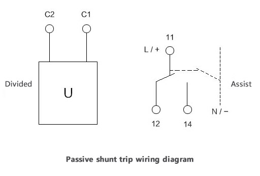
38 shunt trip wiring diagram
Relay Latching Circuit using Push Button - Inst Tools 01/08/2019 · Design a Relay circuit such that it activates whenever PLC sends an trip signal. Also in same time, relay has to activate a Hooter which is powered by 230v AC. And provide a Acknowledge/Reset button to stop the hooter. Note : PLC send a one shot pulse to activate the relay. The realy circuit must hold the signal until it resets by using an Acknowledge/Reset … LiveInternet @ Статистика и дневники, почта и поиск Nous voudrions effectuer une description ici mais le site que vous consultez ne nous en laisse pas la possibilité.
NQ Circuit Breaker Panelboards - DDS (Distributor Data ... Field-installable shunt trip, alarm switch, and other accessories are available for PowerPact H, J, L and LA/LH main circuit breakers. Refer to Catalog 0616CT1001 or 0601CT9101 for additional information. Main Circuit Breaker Adapter Kits NQMB2Q Kit Contents A. Main circuit breaker deadfront cover (1) B. Main circuit breaker mounting pan (1)

Shunt trip wiring diagram
FORMULA - Circuit Breakers Low Voltage - ABB (A-Z Low ... Formula for you. Get quality easily. The SACE FORMULA IEC range consists of four frames (A0, A1, A2 and A3) which reach up 630A, while the SACE FORMULA UL range consists of two frames, A1 and A2, which reach up to 100A and 250A respectively. Motor Control Center Aftermarket Buckets - Eaton B10 Breaker Shunt Trip—120V B11 Breaker Auxiliary Switch—1NO/1NC B19 Breaker Auxiliary Switch—2NO/2NC C10 Control fuse wired for separate source in lieu of CPT C11 Control fuse/disconnect for separate source in lieu of CPT C12 CPT 100VA for size 1 and 2 starters, fused C13 CPT 150VA for size 3 and 4 starters, fused C18 Full capacity CPT for size 5 starters, fused … What is a Shunt Trip Breaker and How Does It Work? 01/02/2022 · Meanwhile, the shunt trip breaker wiring comprises two wires. One connected to the ground, and another to a control system. The control system can be connected to a sensor or to a manual switch. When activated, the shunt trip accessory will cause the main breaker to trip. For example, if you install a shunt trip with a smoke detector, it will activate and cut off the …
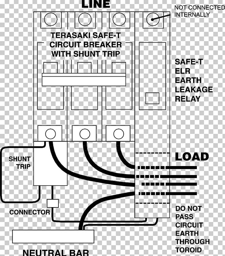
Shunt trip wiring diagram. What is a Shunt Trip Breaker and How Does It Work? 01/02/2022 · Meanwhile, the shunt trip breaker wiring comprises two wires. One connected to the ground, and another to a control system. The control system can be connected to a sensor or to a manual switch. When activated, the shunt trip accessory will cause the main breaker to trip. For example, if you install a shunt trip with a smoke detector, it will activate and cut off the … Motor Control Center Aftermarket Buckets - Eaton B10 Breaker Shunt Trip—120V B11 Breaker Auxiliary Switch—1NO/1NC B19 Breaker Auxiliary Switch—2NO/2NC C10 Control fuse wired for separate source in lieu of CPT C11 Control fuse/disconnect for separate source in lieu of CPT C12 CPT 100VA for size 1 and 2 starters, fused C13 CPT 150VA for size 3 and 4 starters, fused C18 Full capacity CPT for size 5 starters, fused … FORMULA - Circuit Breakers Low Voltage - ABB (A-Z Low ... Formula for you. Get quality easily. The SACE FORMULA IEC range consists of four frames (A0, A1, A2 and A3) which reach up 630A, while the SACE FORMULA UL range consists of two frames, A1 and A2, which reach up to 100A and 250A respectively.
Cutler Hammer A831443-7 Unit Wiring Diagram | Diagram, Wire ...
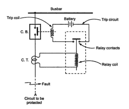
Trip Coil Of Circuit Breaker under Repository-circuits -23149 ...

Shunt Trip Breaker Wiring Diagram, Connection, Circuit - ETechnoG

Earth Leakage Relay Wiring and Connection Diagram - ETechnoG
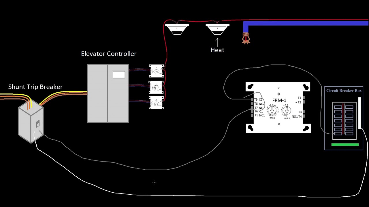
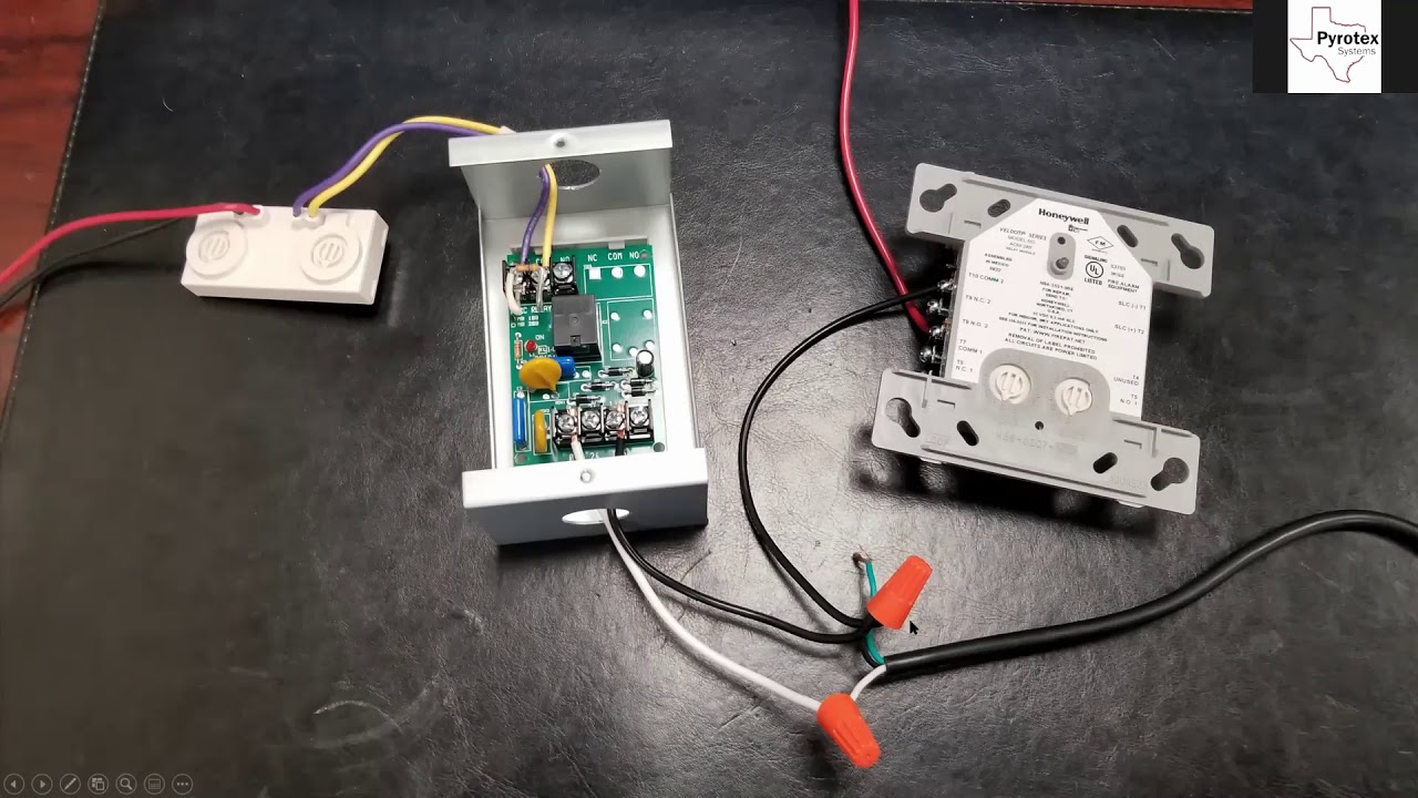
39 - Elevator Shunt Trip - Introduction to Fire Alarms

How to install trip breakers?
Earth Leakage Circuit Breaker Wiring Diagram Relay Fault PNG ...

Shunt Trip Breaker Wiring Diagram
Shunt Trip Wiring

How to shut off intake fan using Ansul system?
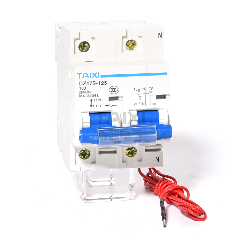
Shunt Trip MCB | 100 Amp Circuit Breaker Shunt Trip - TAIXI ...
Elevator Shunt Trip – Fire Alarm Requirements Here are the ...

Shunt Trip Breaker Wiring Diagram, Connection, Circuit - ETechnoG
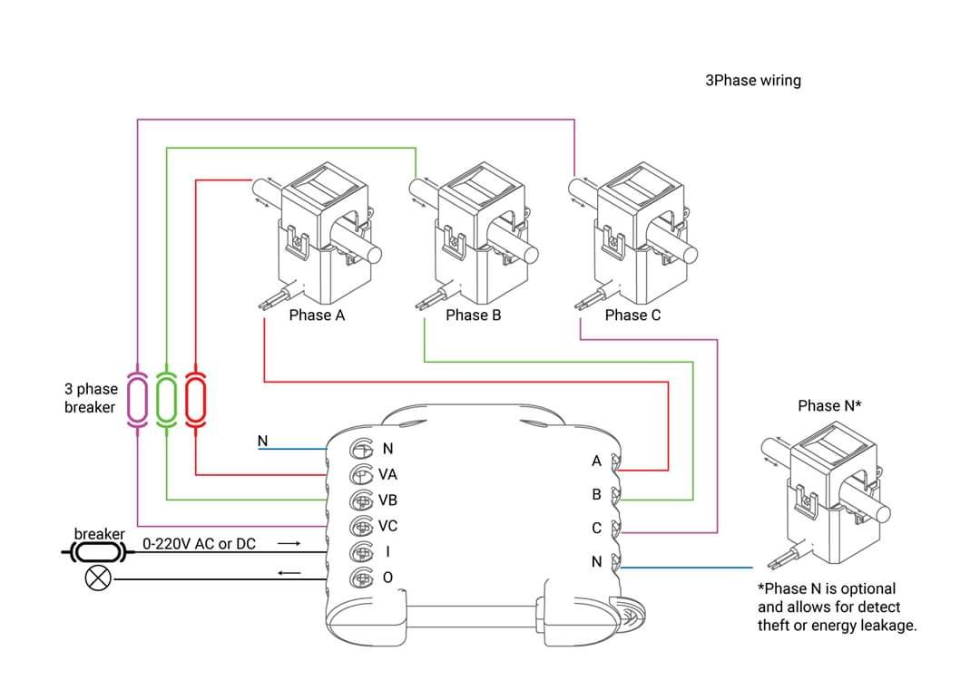
Shelly 3EM mit ioBroker
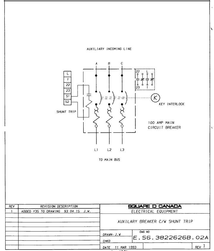
Auxilary Breaker c/w Shunt trip - TM-5-3895-374-24-1_130

China Shunt Release Shunt Trip Sht for MCCB - China Shunt, Trip

Elevator Shunt Trip Requirements and Codes | Fire Alarms Online
Q and M-Frame Circuit Breakers Instruction Leaflet for Shunt Trip
Shunt release trip unit | Circuit breaker component | DADA
SM1 Series Moulded Case Circuit Breakers - Elecal

house wiring diagram: Wire Shunt Trip Breaker Diagramwire ...

Wiring Diagram For Shunt Trip Breaker | Diagram, Breakers, Trip

Shunt Trip Breaker Wiring Diagram Explanation

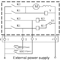
Motor Mechanism
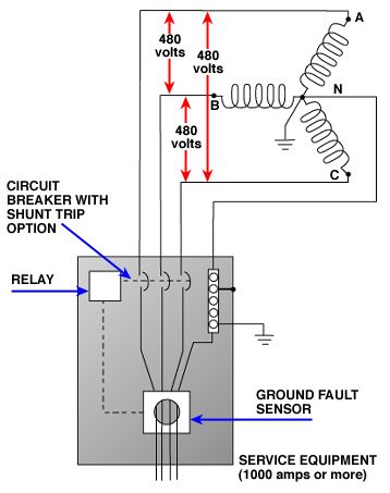
Home Energy Library
Installation Instructions for Series G N-Frame Circuit ...

Shunt Trip Breaker Wiring Diagram, Connection, Circuit - ETechnoG

What is a Shunt Trip? - Electrical Axis
How to Wire a Shunt Trip Breaker Wiring Diagram (DIY Guide)

Motor Mechanism
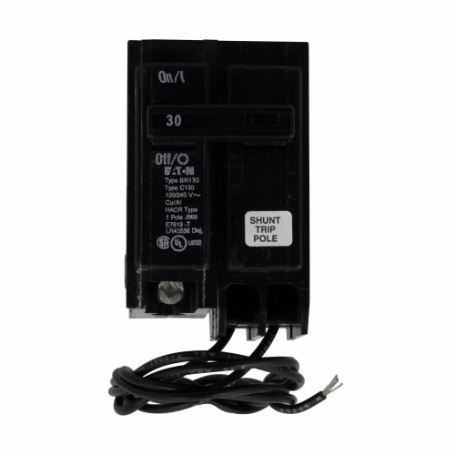
EATON BR125ST | Turtle & Hughes
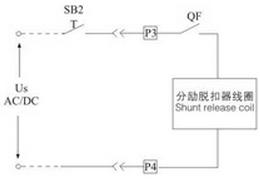
How to wire the circuit breaker shunt trip? | Nader Circuit ...
Ansul wiring check | Electrician Talk
BAB1020S | Eaton BAB thermal magnetic circuit breaker | Eaton
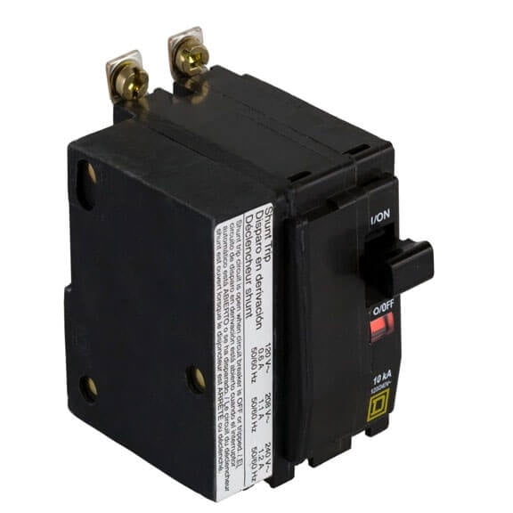
Square D QOB250-1021 2 Pole 50 Amp w/ Shunt Trip
Installation Instructions for Shunt Trip for LDB, LD, HLD ...
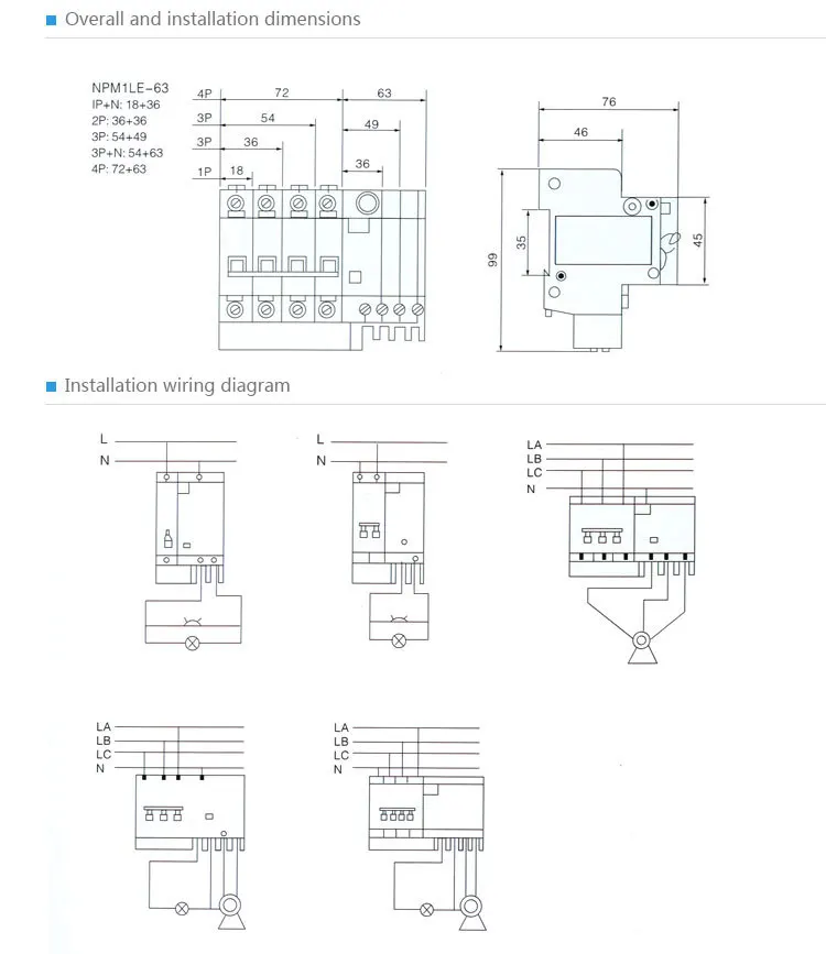
Main Circuit Breaker MCB Shunt Trip Circuit Breaker(SPM1 ...

40 - Elevator Shunt Power Monitor - Introduction to Fire Alarms
0 Response to "38 shunt trip wiring diagram"
Post a Comment