40 hydraulic spool valve diagram
Directional control valve | Directional control valve ... Directional control valves are usually designed to be stackable, with one valve for each hydraulic cylinder, and one fluid input supplying all the valves in the stack. Tolerances are very tight in order to handle the high pressure and avoid leaking, spools typically have a clearance with the housing of less than a thousandth of an inch (25 µm). The Basics Of Hydraulic Spool Valves - CrossCo This valve below has a solenoid on one end and a spring on the opposite end. Now we are going to insert the spool into the body. This is an Eaton-Vickers #2 Spool. By combining the two Pictures, we get a full valve operation. Combined valve operation. Shown here, the valve is in its non-energized position. The Spring is in control.
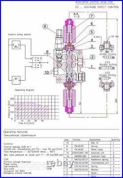
Flow Control Valve with relief Manual - Delavan Fluid Power HYDRAULIC FLOW CONTROL VALVE WITH RELIEF INSTRUCTION MANUAL EXPLOSION DIAGRAM PARTS LIST Rotary Spool kit, Handle Kit, Matering Spool Kit, Relief Kit, They do not sold separately. HYDRAULIC FLOW CONTROL VALVE WITH RELIEF INSTRUCTION MANUAL HYDRAULIC CIRCUIT INSTALLATIONS The valve is mounted as above shown.

Hydraulic spool valve diagram
Hydraulic Spool Valve Diagram - Valves Spool Diagram - Finotek Hydraulic directional spool valve is a relative motion between the valve spool and valve housing, used for controlling fluid-flow direction of actuator motion (movement), select alternative hydraulic oil control circuits, achieve logic control function. The hydraulic spool valves target is to reach different mechanical movement of actuator ... How to Read a Spool Valve Schematic Drawing - RealPars Oct 14, 2019 · Symbols show: – The methods of actuation. – The number of positions. – The flow paths. – The number of ports a valve has. When we see a spool valve schematic, we can see it is made up of boxes, each containing a number of lines and arrows. The number of boxes that make up a valve symbol indicates the number of possible positions the ... Hydraulics Systems Diagrams and Formulas - Cross MFG Winch. The diagram shows a winch powered by a hydraulic motor. The directional control valve with built-in relief features optional flow control to control the speed of the winch . The hydraulic pump and motor must be matched to the torque requirements of the winch.
Hydraulic spool valve diagram. Hydraulics Systems Diagrams and Formulas - Cross MFG Winch. The diagram shows a winch powered by a hydraulic motor. The directional control valve with built-in relief features optional flow control to control the speed of the winch . The hydraulic pump and motor must be matched to the torque requirements of the winch. How to Read a Spool Valve Schematic Drawing - RealPars Oct 14, 2019 · Symbols show: – The methods of actuation. – The number of positions. – The flow paths. – The number of ports a valve has. When we see a spool valve schematic, we can see it is made up of boxes, each containing a number of lines and arrows. The number of boxes that make up a valve symbol indicates the number of possible positions the ... Hydraulic Spool Valve Diagram - Valves Spool Diagram - Finotek Hydraulic directional spool valve is a relative motion between the valve spool and valve housing, used for controlling fluid-flow direction of actuator motion (movement), select alternative hydraulic oil control circuits, achieve logic control function. The hydraulic spool valves target is to reach different mechanical movement of actuator ...
Buy Monoblock Hydraulic Directional Control Valve, 2 Spool ...

VALVE BLOCK, 5 SPOOL - CONSTRUCTION JCB 804 PLUS - MINI ...

Directional Control Valve Basics - Part 1
5 spool hydraulic solenoid directional control valve 13gpm ...
Mobile Directional Control Valve

Directional Control Valves Symbols - Hydraulic Repair Schematic

How to Read a Spool Valve Schematic Drawing - RealPars

The Basics Of Hydraulic Spool Valves - CrossCo

Hydraulic Switching Valves | SpringerLink

Seven spool hydraulicdirectional valve forfarm tractors

Badestnost Hydraulic Spool Valve For Loader Winch,Hydraulic ...

Hydraulic Switching Valves | SpringerLink

How to Read a Spool Valve Schematic Drawing - YouTube ...

HYDRAULIC DAMPER SPOOL VALVE - diagram, schematic, and image 07
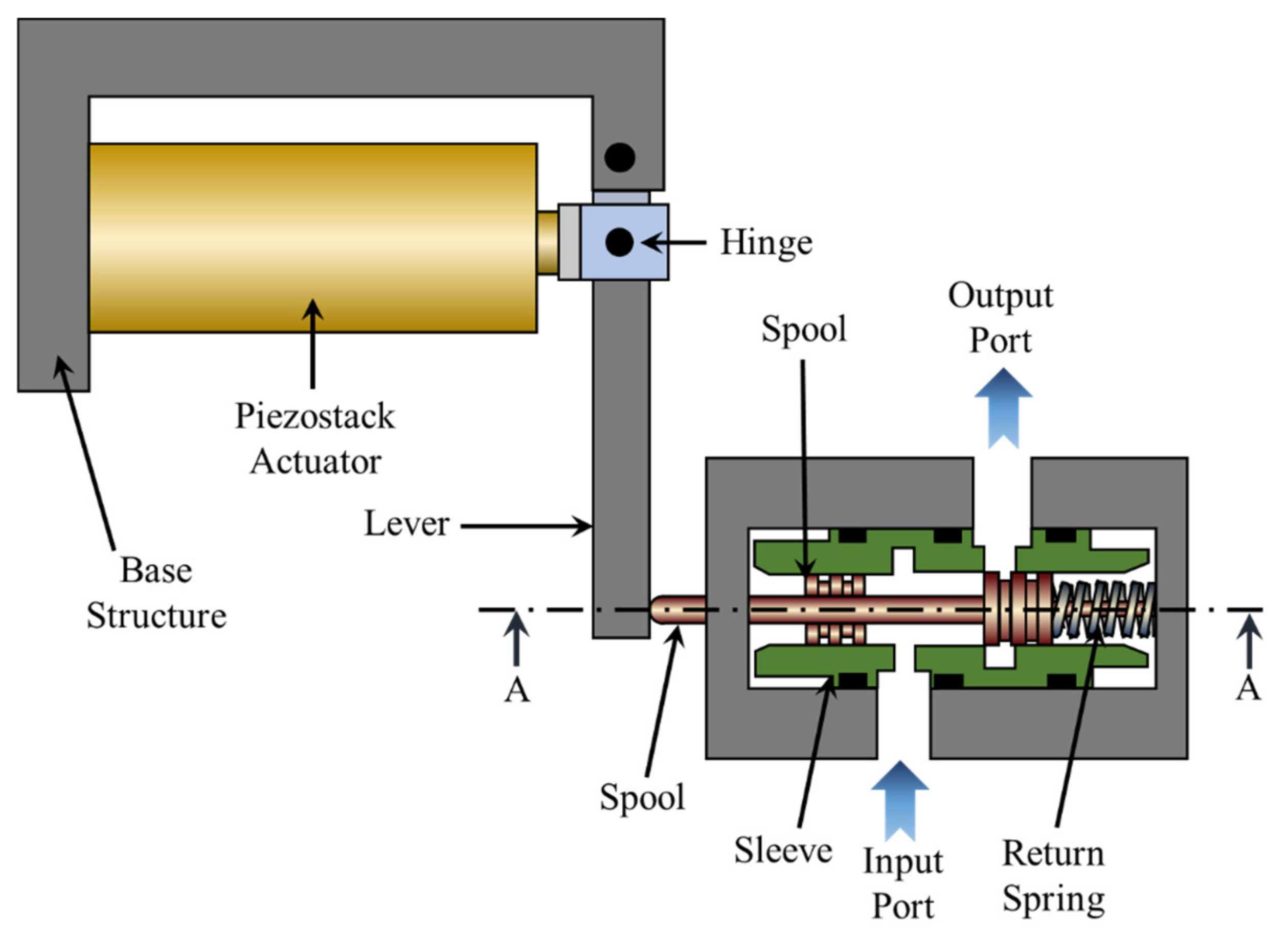
![PDF] Modelling of Hydraulic Spool-Valves with Specially ...](https://d3i71xaburhd42.cloudfront.net/3af4699bb0da814a957c00f6f173debd7a8f83ac/2-Figure1-1.png)
PDF] Modelling of Hydraulic Spool-Valves with Specially ...

HOW TO READ A SPOOL VALVE SCHEMATIC DRAWING

Spool Valve | Cilindro hidráulico, Retroescavadeira, Auto escola

Spool Valve - an overview | ScienceDirect Topics

Hydraulic Actuator with Analog Position Controller - MATLAB ...
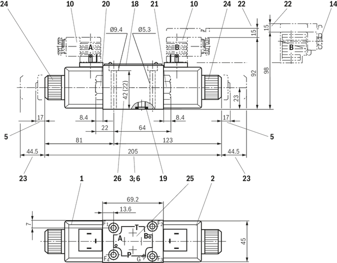
Directional spool valves, direct operated, with solenoid ...

The Most Common Types of Hydraulic Valves - Pneumatic and ...

Hydraulic Four-Way Sliding Spool Valve - Hydraulic ...

Hydraulic Power Systems – Valves (Part One)
Hydraulic Flow Control Valve 3/8" BSP Ports 315Bar 3 Spool 45 l/pm
Monoblock Hydraulic Directional Control Valve, 1 Spool, 21 ...

Monoblock Hydraulic Directional Control Valve, 2 Spool, 11 GPM
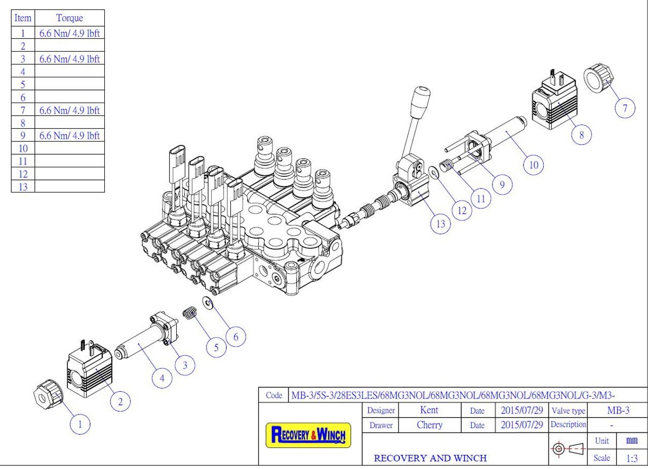
ELECTRO SECTION FOR MB3 HYDRAULIC SPOOL VALVE

VALVE, CONTROL, 3 SPOOL, PARKER REF 3469203245 - CONSTRUCTION ...

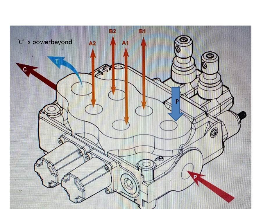
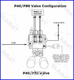
How to configure mobile hydraulic valves using power beyond

Hydraulic Solenoid Valve - How They Work | Tameson.com

What is a spool valve? What are the types of the spool valve ...

How to Read a Spool Valve Schematic Drawing - RealPars

CHAPTER 10: Directional Control Valves, part 4 | Power & Motion

Model BA - 2 Spool Parts | Cross Mfg.

What is a spool valve? What are the types of the spool valve ...

DLDAZ | Cartridges » Directional » 2-way | Sun Hydraulics

What is a Spool Valve and How Does it Work? | RealPars

4 Way 3 position Control Valve Working & Construction

China Leading Manufacturer - Directional Hydraulic Control ...
Actuators | Free Full-Text | The Effect of Spool Displacement ...
0 Response to "40 hydraulic spool valve diagram"
Post a Comment