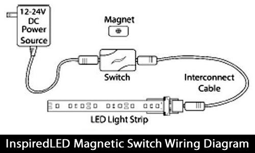
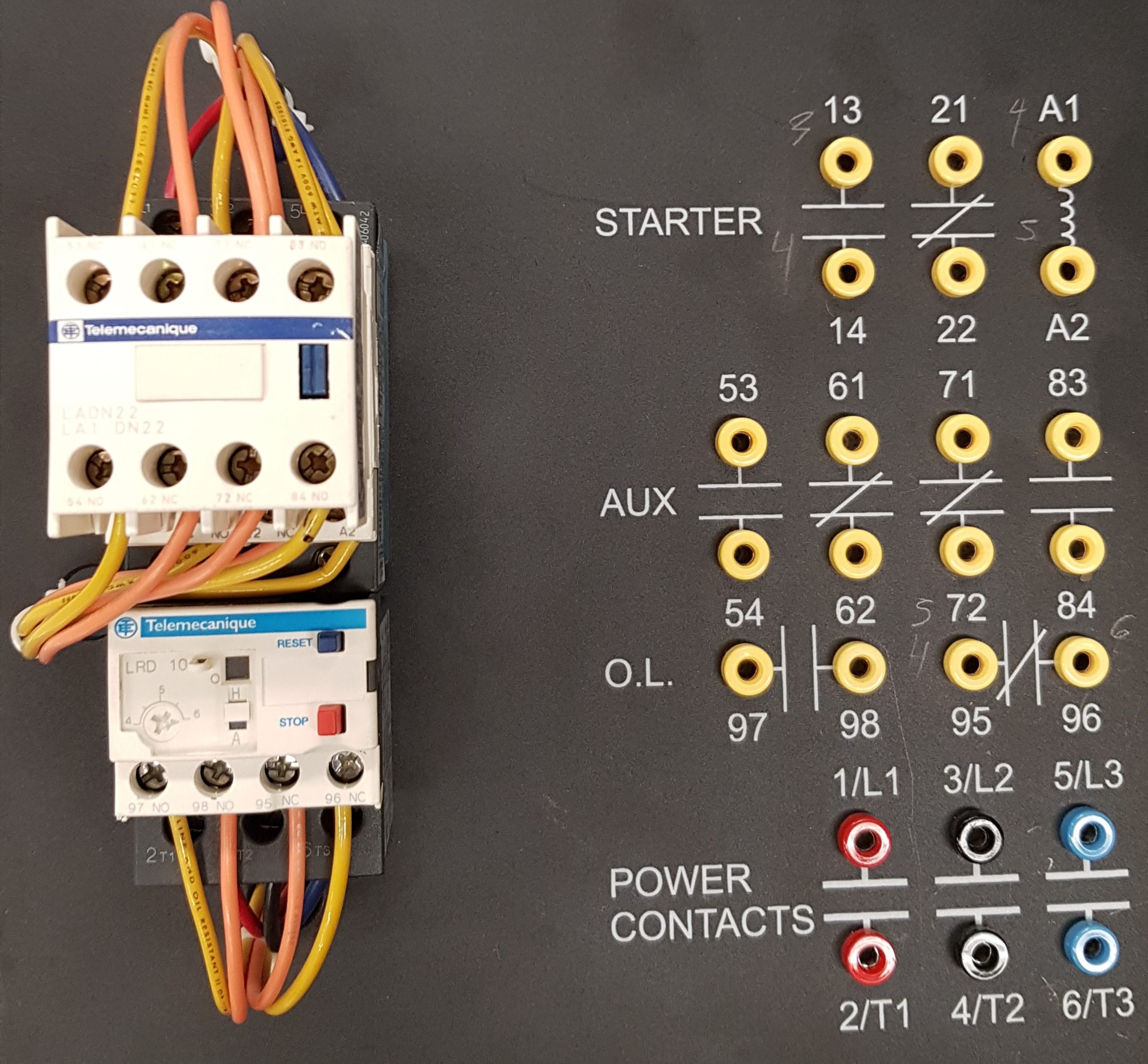
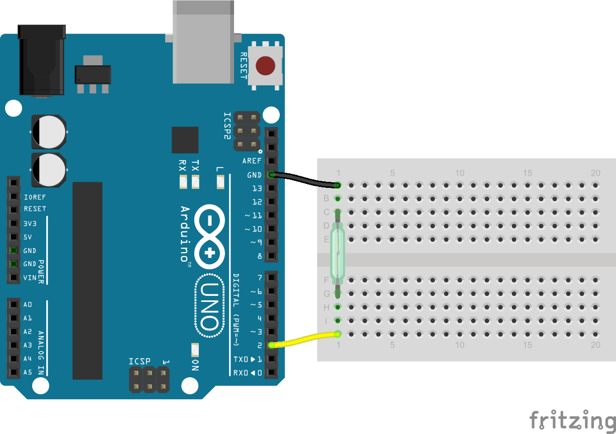
40 magnetic switch wiring diagram
PDF MAGNETIC SWITCH - Detex • Switch - single pole, double throw (SPDT) • The flush device (MS-2049F) should have the switch contact housed in the door frame and the magnet mortised in the edge of the door • Wiring leads, 12" long, color coded, concealed Step by Step Guide on How to Wire the Magnetic Starter on ... This instructional video shows a real person wiring a real magnetic starter attached to a real Atlas Air Compressor. There is nothing complicated about wiri...
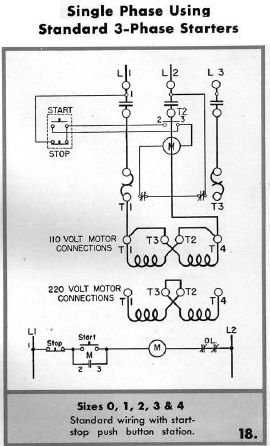
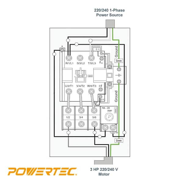
Magnetic Starter Wiring Diagram - easywiring Figure 1 is a typical wiring diagram for a three phase magnetic motor starter. It reveals the elements of the circuit as streamlined forms and also the power and also signal connections between the gadgets. If you have a 120v coil instead of running a line from coil overload l2 you must run coil overload neutral. Shut off the main power.

Magnetic switch wiring diagram
Doorbell Wiring Diagram: A Complete Tutorial | EdrawMax Wiring it wrong will create problems like it may give electric shocks when you press the push button, short-circuit in the chime or the bell button, or it may not produce the sound. The need to make a doorbell wiring diagram comes when you want to make it and supply it to your customers. You always try to avoid any mistakes and try everything ... PDF SI-MAG Non-Contact Magnetic Safety Interlock Switch - Manual SI-MAG Non-Contact Magnetic Safety Interlock Switch for interlocking and position monitoring • A two-piece coded magnetic field safeguarding device • One switch and coded magnet properly placed on a door can achieve the highest levels of safety (Control Reliable, Cat 4, PL e or SIL CL 3) when properly monitored by a Safety Monitoring Module Magnetic Contactor Wiring Diagram Pdf - Wiring Diagram Magnetic contactor wiring diagram pdf. When applying these diagrams it is well to. A wiring diagram gives the necessary information for actually wiring up a group of control devices or for. Manual and magnetic across the line starters may be applied. Magnetic contactor circuit diagram luxury thermal overload relay.
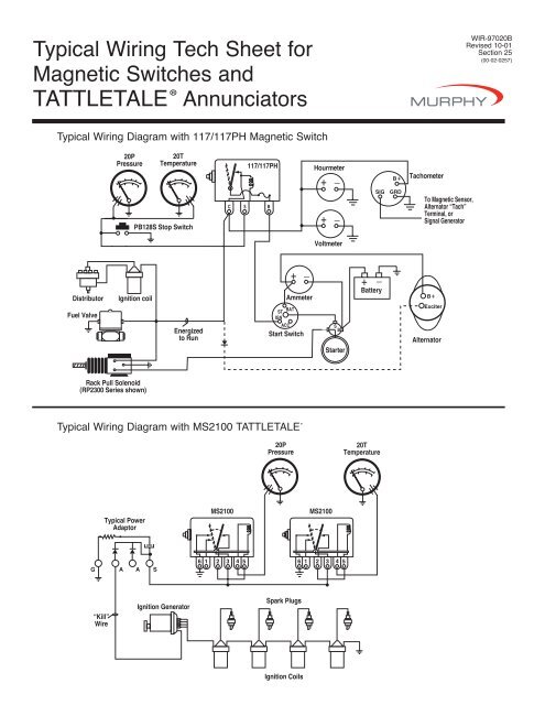
Magnetic switch wiring diagram. Magnetic Contactor Wiring Diagram Three Phase - Irish ... Madcomics Connection 3 Phase Dol Starter Wiring Diagram. Contactor Overload Maintained Switch Wiring For Magnetic Motor. Controls Catalog. Odm General 4 Pole Coil Household 63a Wct Contactor China Made In Com. China Cjx2 2510 220v 3 Pole Wiring Phase Magnetic Contactor Ac. Motor Starter Types Contactor Plc Control. Table Saw Switch Wiring Diagram - easywiring More info about this MAGNETIC switch may help is this in the moter or somewhere else where is it on the drawing. The paddle switch back side shown is on the right. Pin On Electrical Diagrams Craftsman Table Saw Switch Wiring Diagram manualslib CRAFTSMAN Manuals Saw 113 234880View and Download CRAFTSMAN 113 234880 owner s … PDF Typical Wiring Tech Sheet for WIR-97020B Magnetic Switches ... Start Switch Alternator To Magnetic Sensor, Alternator "Tach" Terminal, or Signal Generator B + Energized to Run PB128S Stop Switch Starter S B Exciter R Fuel Valve Typical Wiring Diagram with 760A and 761APH G NO R NC SW1 SW2 B 518PH Jumper* B + SIG GRD + _ Distributor Ignition coil Fuel Valve Rack Pull Solenoid (RP2300 Series shown ... Latching switch - Wikipedia A push-to-make, push-to-break switch would therefore be a latching switch – each time you actuate it, whichever state the switch is left in will persist until the switch is actuated again. Gallery. ABB E256 latching relay Moeller Z-S230 latching relay wiring diagram of latching switch example of latching switch using GE PLS+ relay See also. Latching relay; Toggle …
PDF Magnetic Switch Products - Numatic Engineering Magnetic switch products are designed to signal when an actuator with an integrated magnet has reached a set point in its travel. ... 511 - Wiring Diagrams 511 - Pin and Wire Assignments for Quick Connect 512 - How to Order 513 Heavy Duty Band Mounted Switches PDF Magnetically Operated Switches - Norgren magnetically operated limit switches should not be subjected to: (1) strong magnetic fields, (2) extreme temperature, and (3) excessive ferrous filing or chip buildup. Improper wiring may damage or destroy the switch. The wiring diagram, along with the listed power ratings, must be carefully observed before connecting power to the switch. Typical Wiring Diagram with 117/117PH Magnetic Switch Start Switch Alternator To Magnetic Sensor, Alternator "Tach" Terminal, or Signal Generator B+ Energized to Run PB128S Stop Switch Starter S B Exciter R Fuel Valve Typical Wiring Diagram with 760A and 761APH G NO R NC SW1 SW2 B 518PH Jumper* B+ SIG GRD + _ Distributor Ignition coil Fuel Valve Rack Pull Solenoid (RP2300 Series shown ... Magnetic Starter Wiring Diagram - U Wiring Rewire red wires at coil. Orange Red Blue Blue Black T1 L1 L1 L2 L3 L2 L3 X2 T2 T3 To 208230V Supply COIL 3421 3 To STP see diagram G. MAGNETIC STARTER WIRING DIAGRAMS FOR 30 AMP 110220 VOLT COILS Disconnect all power to the unit before installing or repairing. Coil above is wired for 230 V to pump motor 120 V from Isotrol or dispenser switch.
Eaton Magnetic Starter Wiring Diagram - U Wiring Typical Wiring Diagram Line diagrams show circuits of the operation of the. Eaton magnetic starter wiring diagram. Basic wiring for motor control 36326 ads8 brochure eaton cutler hammer magnetic switch. Eaton motor starter wiring diagram 40 Awesome Square D Model 6 Mcc Wiring Diagram motor control center aftermarket buckets. January 3 2021 1. PDF Wiring Instructions for Magnetic Starters Use the wiring diagrams on the back of this sheet to install and connect power wires for the starter and motor. To ground a factory-mounted starter, ... Switch Magnetic Starter Compressor Base Connect power to the magnetic starter through the knock-out plug in the top of the starter Pressure Switch Compressor Base Magnetic Starter 2008 EZGO Guide - Specs | Price | Manual | Wiring Diagram ... 2008 EZGO wiring diagram. A wiring diagram of your EZGO golf cart can help you gain a clear understanding of the connections in your cart. This can vary among different cart models from the same manufacturer. The wiring diagram of a 2008 EZGO MPT golf cart is … Maglock Wiring Diagram - schematron.org Larger diagram In this example, the manual labeled the blue wire leaving the 6-pin connector as the negative connector to the magnetic lock. The wire we actually use for the connection is the green one that extends past that blue wire and the power. Maglocks can be used on hollow metal, wood, aluminum, glass and composite door materials.
Magnetic Switch for Power Tools - Woodworking Talk Maybe since it's not really a magnetic switch, instructions or a wiring diagram aren't so much needed. All the other things Tool Agnostic said about it are spot on. The screws are too small and it's a bear to get lined up into a box. I'm still looking for a magnetic switch for my 220v 3hp Tools.
PDF Electrical Symbols and Line Diagrams - University of Florida Wiring diagrams show, as closely as possible, the actual location of each ... Magnetic Control Circuits ... Pushbuttons, limit switches, flow switches, foot switches, temperature switches, and pressure switches may be used as the signal section of a control
Tattletale® Annunciators and Magnetic Switches - Enovation ... Magnetic switches and Tattletale annunciators can make or break circuits for these engines. For electric motor application, various magnetic switches are available to operate the motor starter, holding coil directly or in conjunction with appropriate Murphy Transformer-Relay assembly.
› ecm › groupsBasic Wiring for Motor Contol - Eaton Wiring diagrams, sometimes called “main” or “construc-tion” diagrams, show the actual connection points for the wires to the components and terminals of the controller. They show the relative location of the components. They can be used as a guide when wiring the controller. Figure 1 is a typical wiring diagram for a three-phase mag-
magnetic contactor circuit diagram - Wiring Diagram and ... Magnetic Contactor Working Principle Construction Fundamentals. Electromagnetic contactor b overload maintained switch magnetic starter low voltage switching gears working principle vacuum contactors hn series construction timer relay wiring diagram circuit breaker 10 ide drawing contactorotor starters ac cjx8 170 brands induction motor protection system 220v method and png images pngwing ...
PDF Typical Wiring Tech Sheet for Magnetic Switches and ... Start Switch Alternator To Magnetic Sensor, Alternator "Tach" Terminal, or Signal Generator B + Energized to Run PB128S Stop Switch Starter S B Exciter R Fuel Valve Typical Wiring Diagram with 760A and 761APH G NO R NC SW1 SW2B 518PH Jumper* B + SIG GRD + _ Distributor Ignition coil Fuel Valve Rack Pull Solenoid (RP2300 Series shown ...
Magnetic Switch Wiring Diagram - Wiring Tech Magnetic switch wiring diagram. Since Jun 28, How to Wire A Bilge Pump with float switch: A wiring diagram is a simplified standard pictorial representation of an electric circuit. Feb 5, 2020 - Explore Elects Agas's board "Electrical diagram" on Pinterest. If not, the structure won't work as it ought to be.
Access Control Cables and Wiring Diagram | Kisi Magnetic Lock Wiring Diagram. Much like the door access control system diagram above, the mag lock wiring diagram relies on a few simple basics: electricity supply, switches, and, of course, locks. Magnetic locks, also referred to as mag locks or maglocks for short, rely on a constant flow of electricity to stay sealed. When that power is cut, the magnet essentially turns …
Magnetic Switches - Diagrams & Styles - Seaboard Marine Mag Switch, Magnetic Relay, Magnetic Switch, Starter Solenoid What We Do Seaboard Marine delivers "Guaranteed Better Than Factory" Performance, Parts, Design, and Engineering for Cummins and other Marine Diesel applications.
Typical Wiring Tech Sheet for Magnetic Switches and ... Download this article as a PDF (00-02-0257). Typical Wiring Diagram with 117/117PH Magnetic Switch. Typical Wiring Diagram with MS2100 TATTLETALE® Typical Wiring with 518E models
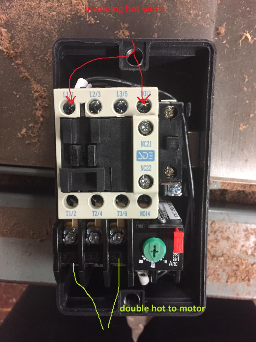
Magnetic Start Switch Wiring to a 5hp Compressor - YouTube Showing how to wire a magnetic start switch along with a pressure switch to a 230 volt single phase 5hp 24 amp compressor. This particular switch is a WEG PE...
PDF Wiring Diagram Book - Daltco w/ Magnetic OL Limit Switches Foot Switches Pressure & Vacuum Switches Liquid Level Switches Temperature Actuated Switches Flow Switches Speed (Plugging) FF R F R Anti-Plug N.O. N.C. Held Closed Held Open ... WIRING DIAGRAM. M A1 A2 M .
Magnetic Door Switch Wiring Diagram Download - Wiring ... Please download these magnetic door switch wiring diagram by using the download button, or right visit selected image, then use Save Image menu. Wiring diagrams help technicians to see what sort of controls are wired to the system. Many people can read and understand schematics generally known as label or line diagrams.
› Documents › 0301710 - 3-wayWireless 1 Identify existing wiring ... Schematic Diagram ... 2 The in-wall switch is UL Listed for use with all magnetic and electronic fluorescent ballasts.
diy.stackexchange.com › questions › 149232electrical - Wiring a Heater, Vent Fan, Light for bathroom ... 24.10.2018 · Can you post photos of the wiring at the switch box, and post the install instructions as well? – ThreePhaseEel. Oct 24, 2018 at 4:14 . 1. Can you replace the cable between switch box and fan? This whole deal would be 10 times easier if you were using /4 cable instead of /2 and /3 cable. Also it would be more legal. – Harper - Reinstate Monica. Oct 24, 2018 at 6:20. …
PDF Magnetic Starter - 30A, 120/240V Coils Wire added by installer Wire added by manufacturer To STP (see diagram G) rjpumps/ms110-220v1.eps NOTE: Coil above is wired for 230 V to pump motor, 120 V from Isotrol or dispenser switch. (Remove red wire connecting X2 to L2). Rewire red wires at coil. Orange Red Blue Blue Black T1 L1 L1 L2 L3 L2 L3 X2 T2 T3 To 208/230V Supply COIL 3421 3 To ...
Magnetic Switch Wiring Diagram Download - Wiring Diagram ... magnetic switch wiring diagram - What's Wiring Diagram? A wiring diagram is a kind of schematic which uses abstract pictorial symbols to exhibit every one of the interconnections of components in the system.
› faq-wiringTrailer Wiring Diagrams | etrailer.com Standard 4-Pole Wiring Harness - For use with vehicles that have adequate power and standard wiring system, these simply connect into existing wires on the vehicle and have a 4-pole flat connector to attach a trailer. Converter - For use with vehicles that have separate turn and brake light wires. Some vehicles send only one signal per wire ...
Magnetic Contactor Wiring Diagram Pdf - Wiring Diagram Magnetic contactor wiring diagram pdf. When applying these diagrams it is well to. A wiring diagram gives the necessary information for actually wiring up a group of control devices or for. Manual and magnetic across the line starters may be applied. Magnetic contactor circuit diagram luxury thermal overload relay.
PDF SI-MAG Non-Contact Magnetic Safety Interlock Switch - Manual SI-MAG Non-Contact Magnetic Safety Interlock Switch for interlocking and position monitoring • A two-piece coded magnetic field safeguarding device • One switch and coded magnet properly placed on a door can achieve the highest levels of safety (Control Reliable, Cat 4, PL e or SIL CL 3) when properly monitored by a Safety Monitoring Module
Doorbell Wiring Diagram: A Complete Tutorial | EdrawMax Wiring it wrong will create problems like it may give electric shocks when you press the push button, short-circuit in the chime or the bell button, or it may not produce the sound. The need to make a doorbell wiring diagram comes when you want to make it and supply it to your customers. You always try to avoid any mistakes and try everything ...














0 Response to "40 magnetic switch wiring diagram"
Post a Comment