40 mallory ignition wiring diagram
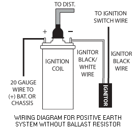
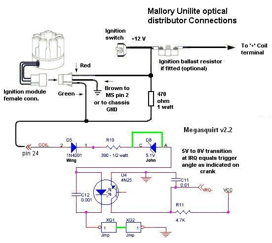
Popular Mallory Ignition Coil Wiring Diagram You Must Know Mar 16, 2022 · Mallory unilite distributor wiring diagram wiring site resource from lh6.googleusercontent.com before installing the unilite distributor, make sure that your vehicle is equipped with an ignition ballast resistor (or loom resistance wire) in the wire between the ignition switch and the coil (+) terminal. Mallory Electronic Distributor Wiring Diagram Nov 15, 2018 · GM HEI Wiring Schematic, Mallory Distributor Identification, Mallory Electronic Ignition Wiring Diagram, Mallory Unilite Distributor Problems. 2) If your vehicle is equipped with a HyFire Electronic Ignition Control or similar aftermarket ignition control, use the wiring wire, such as Mallory PRO SIDEWINDER® Ignition Wire.
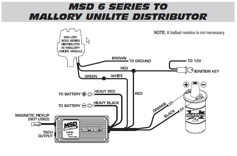
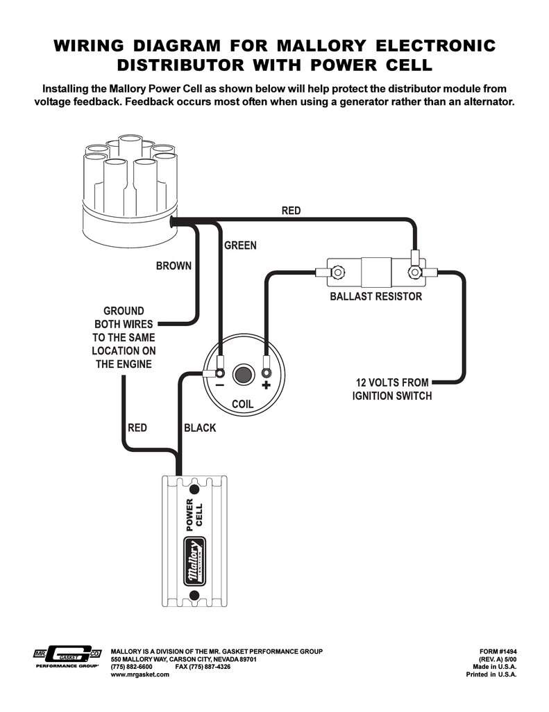
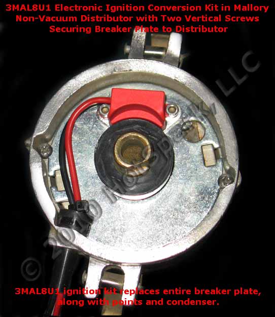
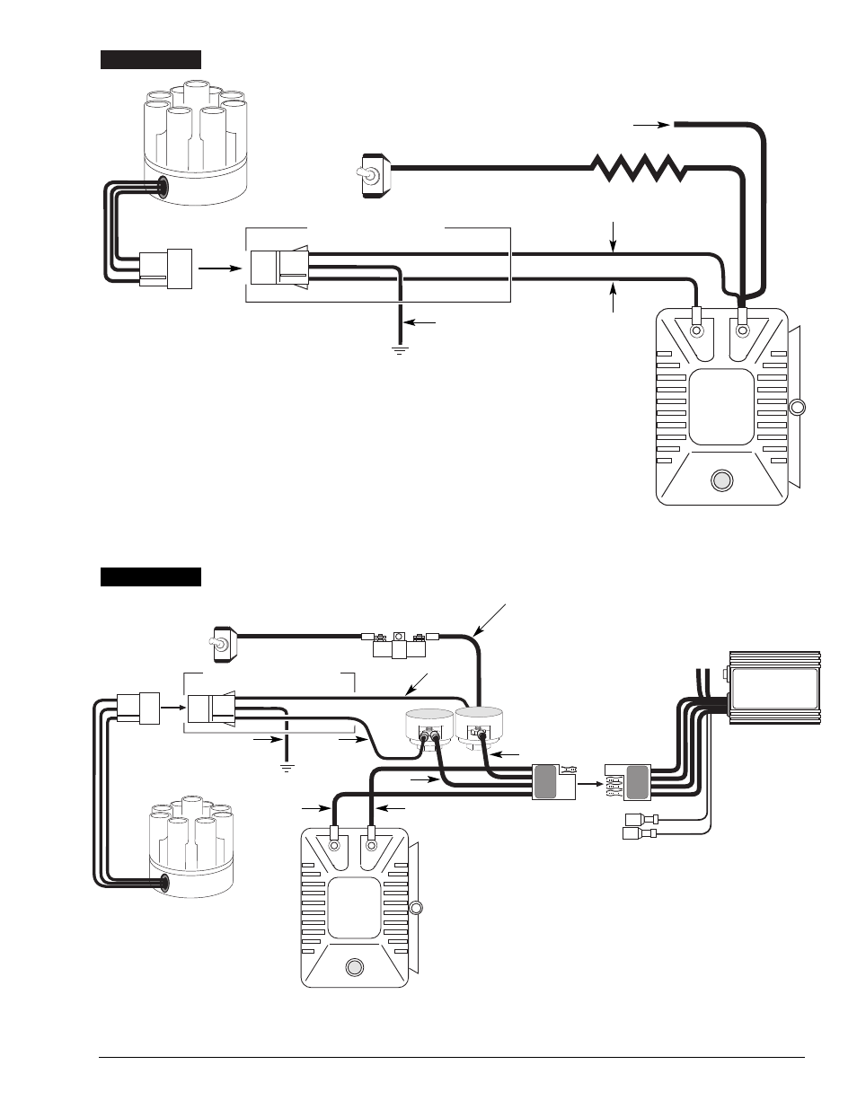
Mallory Unilite Ignition Wiring Diagram 10) Start the three wires of the Mallory UNILITE® Module through the hole in the nose 14) Route the wires from the UNILITE® Module to the ignition coil, carefully 16) Follow a factory shop manual to set the timing for your particular engine.Wiring Diagram for Mallory Distributer Don't worry if your coil doesn't look like this American one, or ...
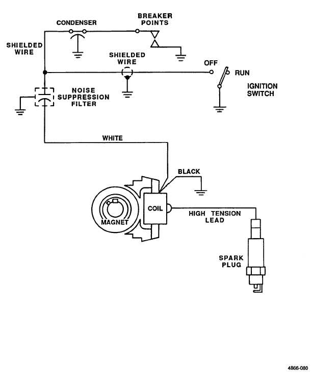
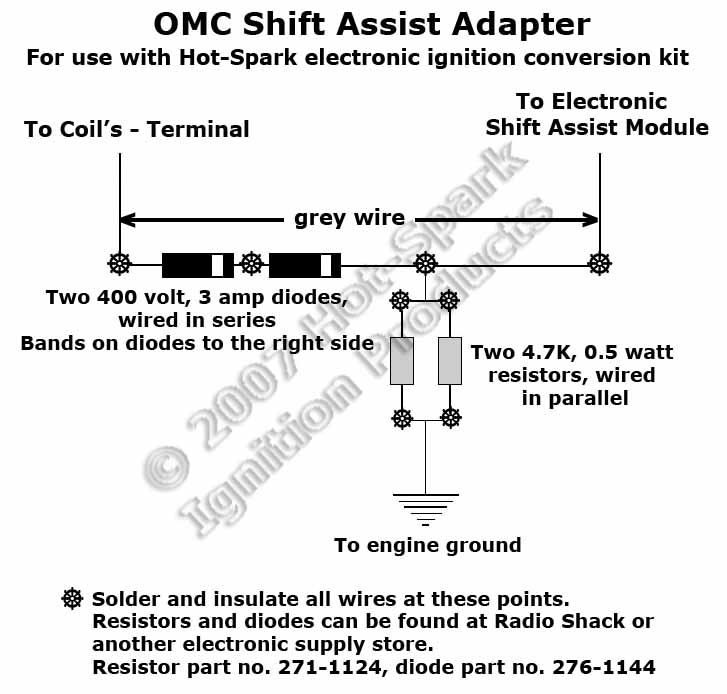
Mallory ignition wiring diagram
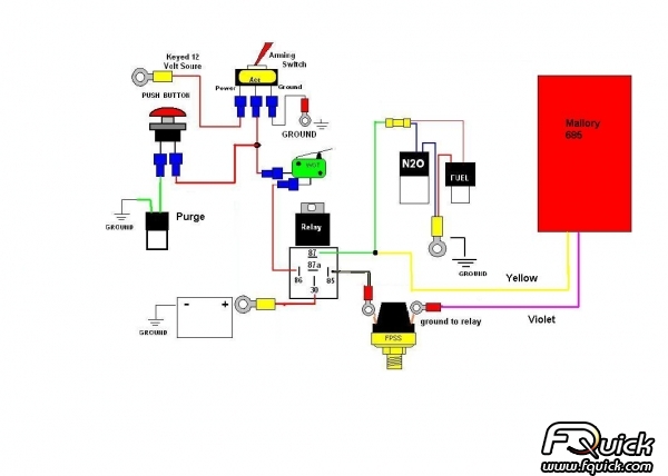
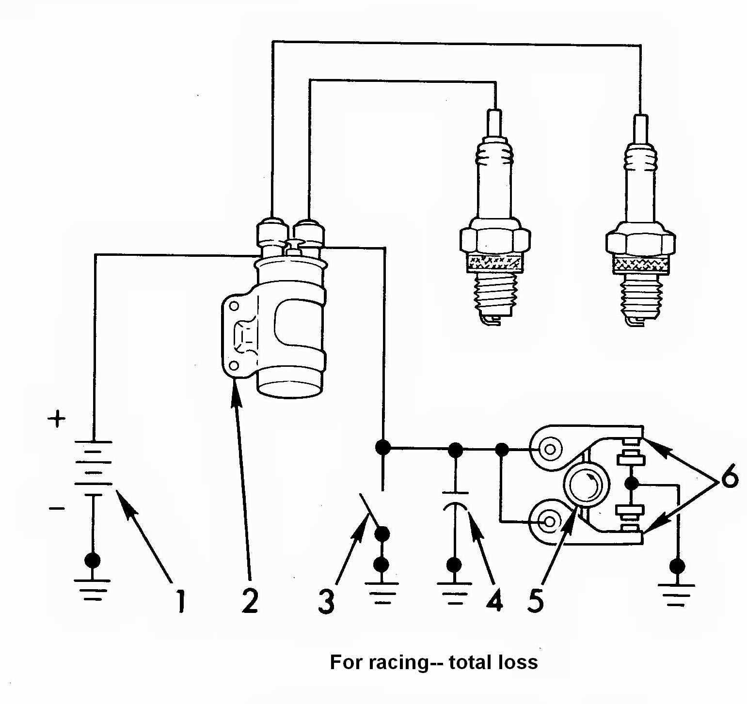
Mallory Unilite Distributor Installation Instructions 2 MALLORY IGNITION-+ COIL FIGURE 1 UNILITE® WIRING DIAGRAM USING BALLAST RESISTOR NOTE: The purpose of an ignition ballast resistor between the ignition switch (12V) and the ignition coil positive terminal is to restrict current flow through the ignition coil. Failure to use an ignition ballast resistor will PART NOS. 6852M (6-A) and 6853M (6-AL) - Holley Ignition Control: a points circuit (white wire) or a magnetic pickup circuit (violet and green wires). NOTE: The two circuits will never be used together. White Connects to points, electronic ignition amplifier output or to the green wire of a Mallory timing accessory.When this wire is used, the magnetic pickup connector is not used. Mallory Ignition Wiring Diagram - Free Wiring Diagram Feb 07, 2022 · Collection of mallory ignition wiring diagram. A wiring diagram is a simplified standard pictorial depiction of an electrical circuit. It shows the components of the circuit as streamlined forms, as well as the power and also signal links between the tools.
Mallory ignition wiring diagram. Mallory Ignition Wiring Diagram - Free Wiring Diagram Feb 07, 2022 · Collection of mallory ignition wiring diagram. A wiring diagram is a simplified standard pictorial depiction of an electrical circuit. It shows the components of the circuit as streamlined forms, as well as the power and also signal links between the tools. PART NOS. 6852M (6-A) and 6853M (6-AL) - Holley Ignition Control: a points circuit (white wire) or a magnetic pickup circuit (violet and green wires). NOTE: The two circuits will never be used together. White Connects to points, electronic ignition amplifier output or to the green wire of a Mallory timing accessory.When this wire is used, the magnetic pickup connector is not used. Mallory Unilite Distributor Installation Instructions 2 MALLORY IGNITION-+ COIL FIGURE 1 UNILITE® WIRING DIAGRAM USING BALLAST RESISTOR NOTE: The purpose of an ignition ballast resistor between the ignition switch (12V) and the ignition coil positive terminal is to restrict current flow through the ignition coil. Failure to use an ignition ballast resistor will









0 Response to "40 mallory ignition wiring diagram"
Post a Comment