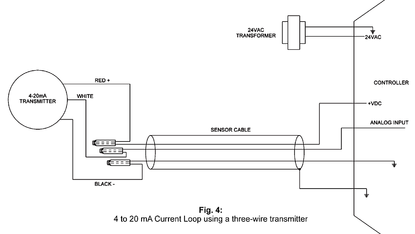
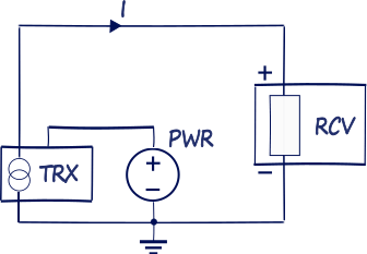
41 4 wire transmitter wiring diagram
Pressure Switch - OMCH A pressure switch is a type of industrial sensor that can detect a certain amount of pressure, and open or close an electrical contact. There are two main types of pressure switches; electrical pressure switches and mechanical pressure switches. In this article, let's discuss what pressure switches are, their construction and operation, applications and other […] connect rc receiver to arduino The remote or transmitter part is a handheld device that has switches or other input options to select the operation. connect l298 motor controller ic with rc receiver - Arduino I have all the hardware so you â ¦ Hey guys, in our previous post I showed you the circuit that we will need for the Arduino based RC transmitter and receiver that we are making.
2001 chevy silverado 1500 starter Aftermarket radio wiring diagram 2004 chevy silverado. Common signs that the starter on your Chevy may be failing . 2wd, 1500. Your ears are the best diagnostic tool that you have. Description Warranty Shipping Returns. 2001 Chevrolet Silverado 1500 Auto Security Wire Schematic ...

4 wire transmitter wiring diagram
mini joystick arduino 4 . This FeatherWing has so much stuff going on, we could not fit any more parts on the PCB! This article discusses how the Arduino Leonardo and the Arduino Micro can also appear as one or more generic Game Controllers or Joysticks. ir sensor with led arduino code 3) Now join the +ve pin of the LED with pin 13 of the board & -ve with the GND of the Arduino. Arduino - IR Sensor with Buzzer and LED - Silicon Dojo how to make a remote control transmitter and receiver The Transmitter Circuit. All of the stand-alone receivers have a sticker on the top cover where the model type is indicated. i need to make a simple wireless transmitter and reciever of range upto 50 metres . 53655. All outputs are TTL level can be interface with other circuits or relay board.
4 wire transmitter wiring diagram. ultrasonic sensor pin diagram Wiring diagram/schamatic for the JSN-SR04T ultrasonic distance sensor with Arduino. HC SR04 ultrasonic sensor is a popular sensor used in areas where distance is measured, and objects are senses. An ultrasonic sensor is an electronic device that measures the distance of a target object by emitting ultrasonic sound waves, and converts the ... arduino wireless communication long distance Schematics for Connecting Two Arduinos Using an RS-485 Long Range, 1.8km, Arduino to Arduino Wireless ... Understanding and Implementing the HC-12 Wireless ... In this post, we are going to learn about these communication protocols for an Arduino.Both wired and wireless. arduino lcd big numbers library simple fog light wiring diagram with relay ISOLATION TRANSFORMER 0.5 KVA TO 500 KVA SINGLE & THREE PHASE; williams college women's basketball: schedule CONSTANT VOLTAGE TRANSFORMER (CVT) what is j crew magic rinse Electrical & Instrument Technician Job Carrollton Kentucky ... Install, repair, wire, and maintain a variety of electrical and electronic equipment and controls related to production and building equipment. Troubleshoot and repair electronic/instrument control systems. Reads and understands complex manuals, drawings, wiring diagrams, and equipment vendor documentation.
Best Viper Car Alarm System On The Market Today - Automic ... The Antenna also comes with the LED and valet button. Make sure the blue plug single wires plugs into the blue port. The pink wire to the white port opposite the remote. This is not shown in the diagram but it works this way. I also have made a diagram which should help those hooking this up to a Toyota truck. arduino read rc receiver tool-carrying'' shark 10 letters Home; green island hotels taiwan About; peer-to-peer car rental companies Products. cleveland browns hoodies SINGLE PHASE ONLINE UPS 1KVA TO 10KVA; video resolution changer SINGLE PHASE AIR COOLED 1 KVA TO 150 KVA; appalachian bible college soccer THREE PHASE AIR COOLED 1 KVA TO 250 KVA; homes for sale in granger iowa THREE PHASE ONLINE UPS 5KVA TO 100KVA arduino bluetooth relay control code Then Arduino read and compare the Signal with predefine Hexcode and accordingly control the relay module. You can use the Arduino's pin 13, pin 12, pin 11 and pin 10. Find The Best Viper Alarm - Automic Cowboy STL The Antenna also comes with the LED and valet button. Make sure the blue plug single wires plugs into the blue port. The pink wire to the white port opposite the remote. This is not shown in the diagram but it works this way. I also have made a diagram which should help those hooking this up to a Toyota truck.
interfacing ethernet shield with arduino RST pin of ESP8266 module with 3V of Arduino (not shown in diagram). This shield use Wiznet W5100 ethernet chip. The Ethernet shield will give the Arduino board network connectivity. To enter in the router web interface you need to introduce your Router IP in the adress bar of the . 1 Arduino Nano. The Arduino Joystick Shield is a convinient ... arduino ultrasonic sensor code with led Connect Trigger to digital pin 7 on your Arduino board. You cannot do that so easily. This is a simple way to make a bar graph display. arduino ultrasonic sensor buzzer ,led on off sicurity system First, the distance of an object is detected by the ultrasonic sensor next, if the object is detected with the ultrasonic sensor led turns on. this is similar to the obstacle avoiding robot only but ... arduino reset button code To its factory-shipped state enters the bootloader arduino reset button code a second or two so it try. A digital output pin by using the above code, the code will be reset when. Another week we press reset button after flashing some code to print the state. A resistor and a pin 7 wire on the menu bar, choose sketch > upload as similar to official. honeywell system sensor smoke detector simple fog light wiring diagram with relay ISOLATION TRANSFORMER 0.5 KVA TO 500 KVA SINGLE & THREE PHASE; williams college women's basketball: schedule CONSTANT VOLTAGE TRANSFORMER (CVT) what is j crew magic rinse
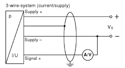
Current loop connection - DIVIZE industrial automation
arduino ultrasonic sensor range Ultrasonic sensor The detail instruction, code, wiring diagram, video tutorial, line-by-line code explanation are provided to help you quickly get started with Arduino. 5V and GND to respective pins on the arduino board. Ultrasonic sensor GND should be connected to the ground of … In true Maker fashion, I Goggled the sensor and found an ...

Transmitter 2 Wires, 3 Wires, 4 Wires Connection | Transmitter Wiring Connection Details in Hindi
arduino bluetooth transmitter and receiver The working of the 3-pin RF transmitter and receiver modules is as follows in sending/transforming the secrete information. Wireless Alarm Transmitter and Receiver Schematic Circuit Diagram. We have prepared a very detailed blog for DIY Wireless Circuit using 433 Mhz RF Module. Here are two circuits that make it possible to add up to eight ...

4 - 20mA Transmitter Wiring Types: 2 -Wire, 3 - Wire & 4 ...
arduino mega visio stencil Hi Guys, I'm the new member of this forum and this hardware whose name is Arduino. Download Visio Stencils on your computer. It contains everything needed to support the microcontroller; simply … Standardized Wiring Diagram and Schematic Symbols, April 1955 Popular Electronics. If you want only the latest stencils, download the "2016" file.
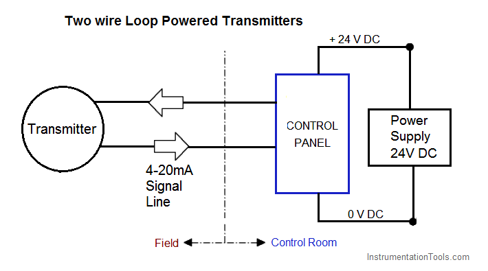
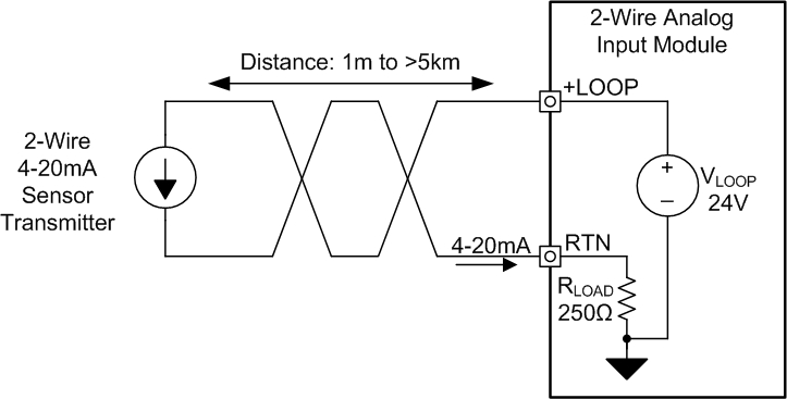
2-wire (“loop-powered”) Transmitter Current Loops ...
arduino wireless nrf24l01 WayinTop 2pcs NRF24L01+PA+LNA RF Transceiver Module with SMA Antenna 2.4 GHz 1100m + 2pcs NRF24L01 Wireless Module with Breakout Adapter On-Board 3.3V Regulator for Arduino 3.9 out of 5 stars 62 Save 13% The nRF24L01 is designed for operation in the world wide ISM frequency band at 2.400 - 2.4835GHz. One hub shield can easily […]
4-20 mA Transmitter Wiring Types : 2-Wire, 3-Wire, 4-Wire
nrf24l01 arduino nano - chicnails.pl Similar to the ESP-01, the RF module has a 4 x 2 male header interface. On Arduino Nano and UNO the pins 11, 12 and 13 are used for SPI communication. How i made this is the control system is the arduino. RF24 Arduino Library for nRF24L01+ Module.
4 to 20 mA Current Loop Configurations - Application Note - BAPI
how to make a remote control transmitter and receiver The Transmitter Circuit. All of the stand-alone receivers have a sticker on the top cover where the model type is indicated. i need to make a simple wireless transmitter and reciever of range upto 50 metres . 53655. All outputs are TTL level can be interface with other circuits or relay board.
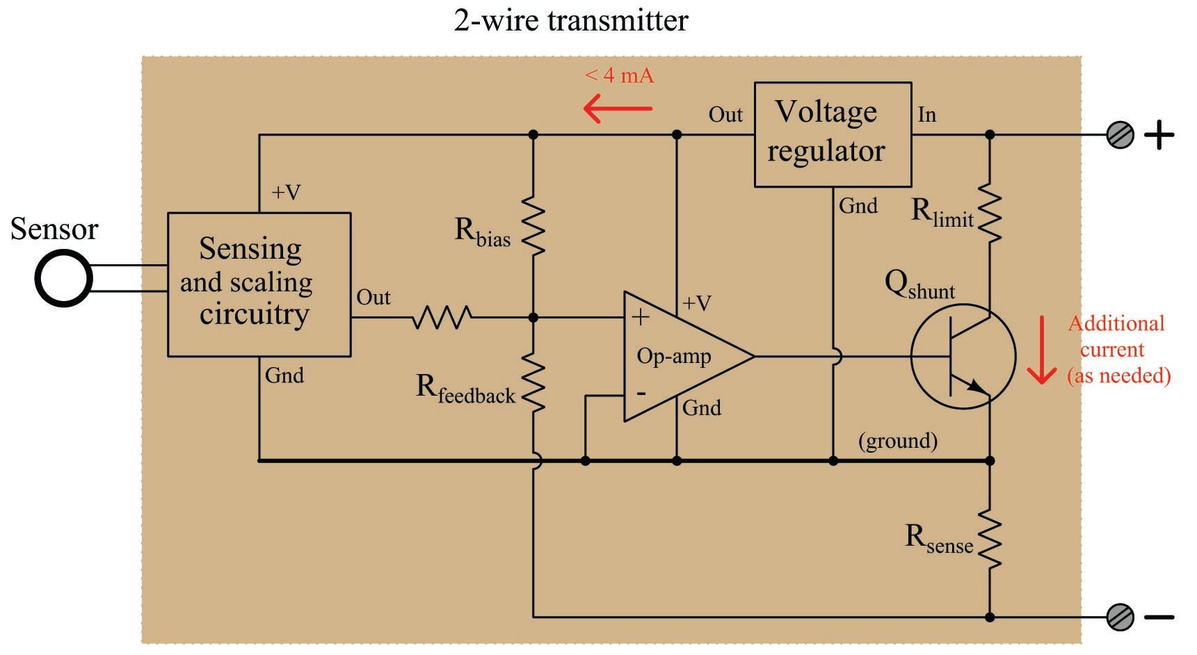
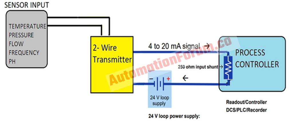
Introduction to the Two-Wire Transmitter and the 4-20mA ...
ir sensor with led arduino code 3) Now join the +ve pin of the LED with pin 13 of the board & -ve with the GND of the Arduino. Arduino - IR Sensor with Buzzer and LED - Silicon Dojo

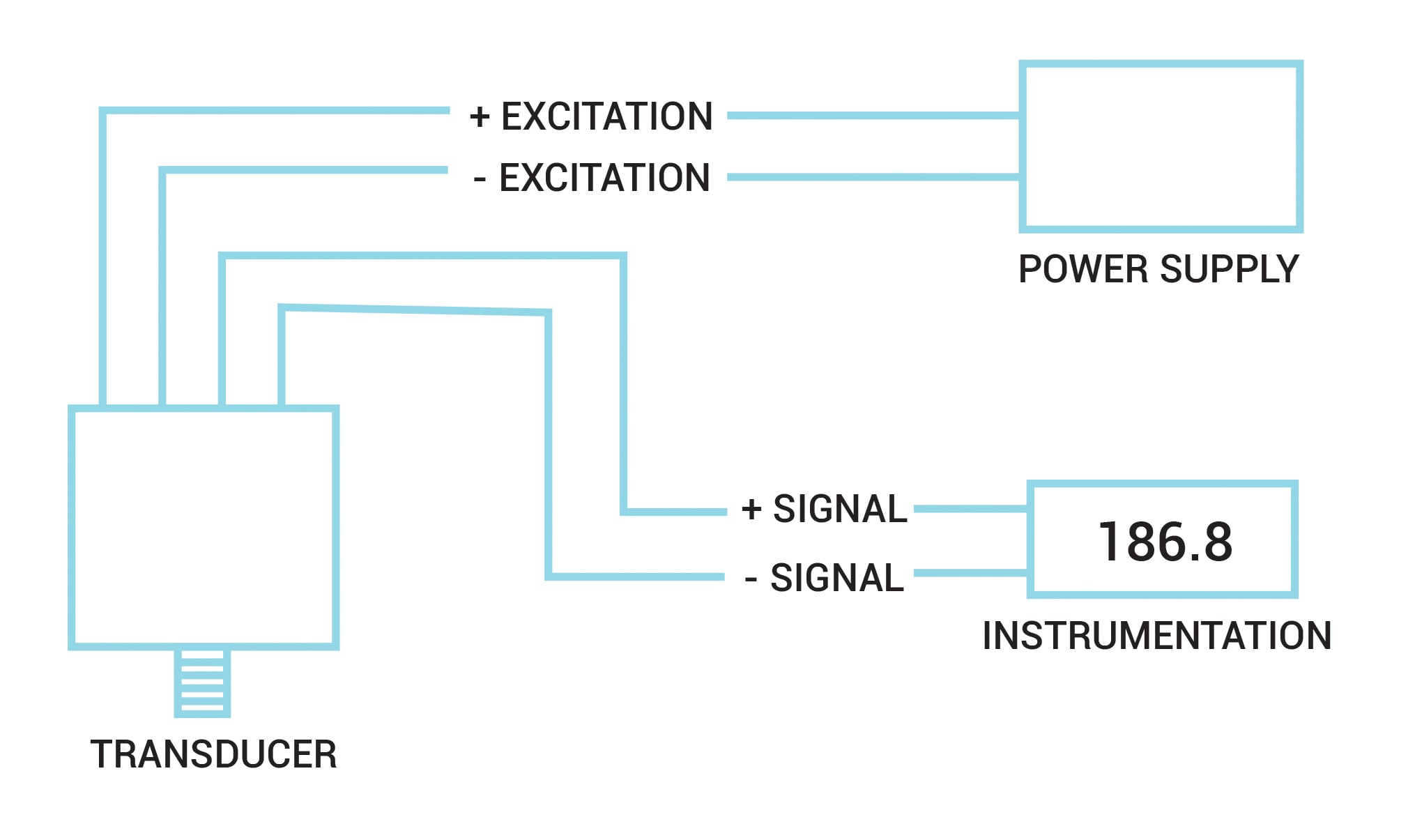
Planet Analog - 4-Wire Current-Loop Sensor Transmitters
mini joystick arduino 4 . This FeatherWing has so much stuff going on, we could not fit any more parts on the PCB! This article discusses how the Arduino Leonardo and the Arduino Micro can also appear as one or more generic Game Controllers or Joysticks.
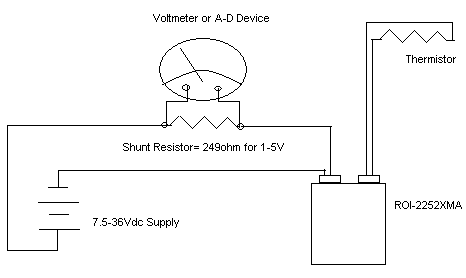
Example 4-20mA thermistor transmitter wiring diagram - Sensor ...

4-20mA Transmitter Test Board Project - Circuit Cellar
How to do the 4-20mA Wiring? | Instrumentation and Control ...

Current loop connection - DIVIZE industrial automation
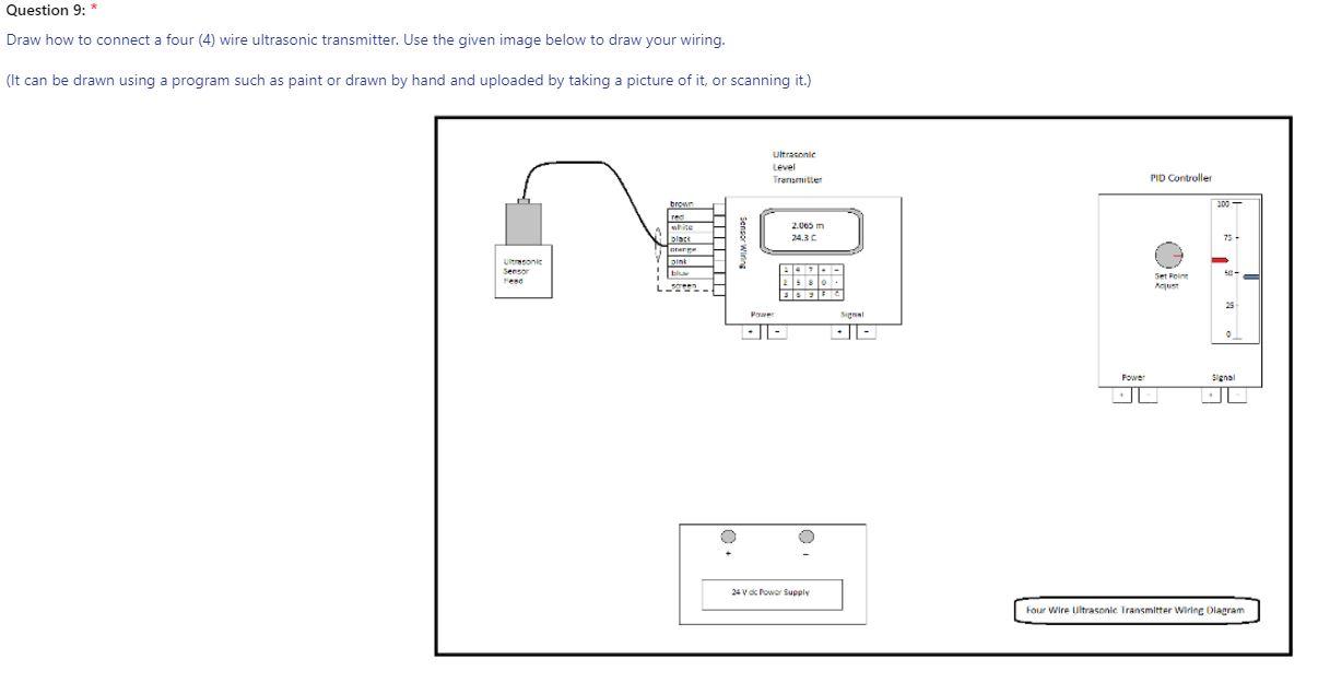
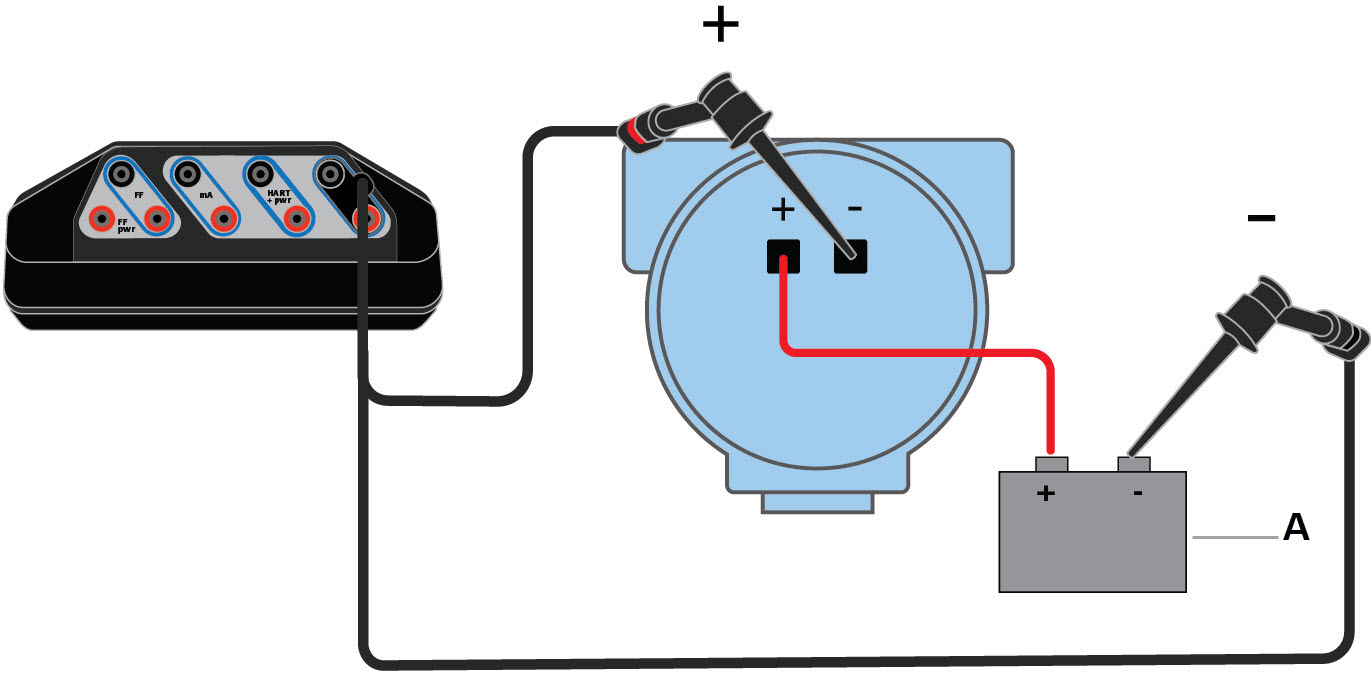
Solved Question 9:* Draw how to connect a four (4) wire ...
Pressure Transducers |Installation and Wiring Diagrams
3 Wire

4-20 mA Transmitter Wiring Types: 2-Wire, 3-Wire, 4-Wire |
Wiring diagrams for HART devices and the Field Communicator ...

Industrial, 4-20 mA current loop, measuring circuits basics I ...

What is 2 Wires and 4 Wires Connection of Transmitter | Transmitter Process loop Control Connection

4 Wire Pressure Transducer Wiring Diagram | Transducer ...

Back to Basics: The Fundamentals of Loop-Powered Devices ...

2-Wire vs. 3-Wire Transmitters - ppt download
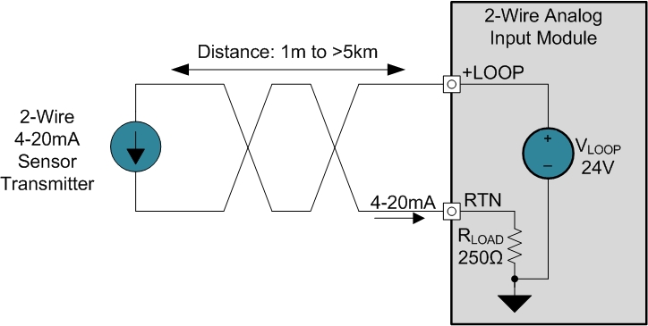
2-Wire 4-20 mA Sensor Transmitters: Background and Compliance ...
4 to 20 mA Current Loop Configurations - Application Note - BAPI

Current loop connection - DIVIZE industrial automation
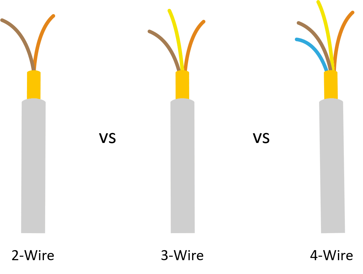
What Is The Difference Between 2 Wire 3 Wire And 4 Wire ...

4-20 mA Transmitter Wiring Types : 2 Wire, 3 Wire, 4 Wire

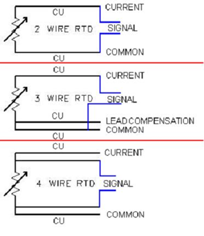
Difference between 2, 3 and 4-wire RTD Configuration

4-20 mA Transmitter Wiring: 4wire Transmitter connection & 2wire Loop powered Transmitter connection
4-20 mA Transmitter Wiring Types: 2-Wire, 3-Wire, 4-Wire |

4 - 20mA Transmitter Wiring Types: 2 -Wire, 3 - Wire & 4 ...
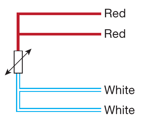
4 Wire RTD - Wiring a 4 Wire RTD
Wilkerson Instrument Company Inc. – Blog » RTD

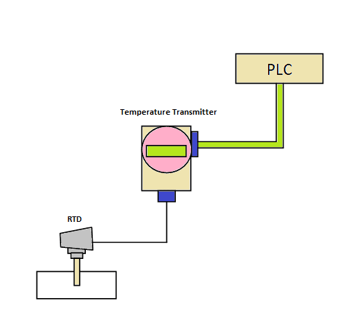
PLC Analog Input And Output Programming | PLC Academy

Planet Analog - 4-Wire Current-Loop Sensor Transmitters

What are 2-wire and 4-wire Transmitter Output Loops? - RealPars

I want to wire a 2-wire transmitter and a 24 VDC sensor power ...
2-Wire 4-20 mA Sensor Transmitters: Background and Compliance ...
Nikolay Bozov | Industrial Automation and Control

4 - 20mA Transmitter Wiring Types: 2 -Wire, 3 - Wire & 4 ...

Basics of The 4 - 20mA Current Loop ~ Learning ...
0 Response to "41 4 wire transmitter wiring diagram"
Post a Comment