42 heat pump ts diagram
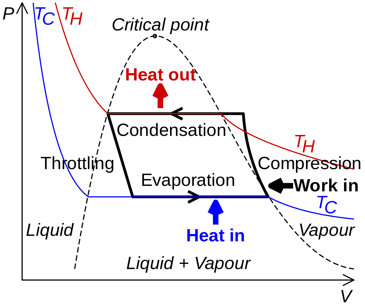
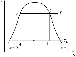
PDF Met -303 thermal ENGINNERING-1 | heat transfer A heat pump is a reversed heat engine. It receives heat from a low temperature reservoir. (source) and rejects it to high temperature reservoir (since) for which an S (b) TS diagram. Process 2-3 (adiabatic expansion). The working fluid expands through a turbine or expander adiabatically producing a net... English: Ts diagram of a transcritical heat pump DescriptionTs transcritical heat pumps.png. English: Ts diagram of a transcritical heat pump.
Refrigeration Basics and LNG - University of Oklahoma Figure 2-8: TS and P-H diagram for liquid sub-cooling in a refrigeration cycle. Exercise 2-4: Implement the sub-cooling cycle in Pro II and report the new COP. Compare it with the dry cycle without sub-cooling and the Carnot cycle. Use streams E and F …
Heat pump ts diagram
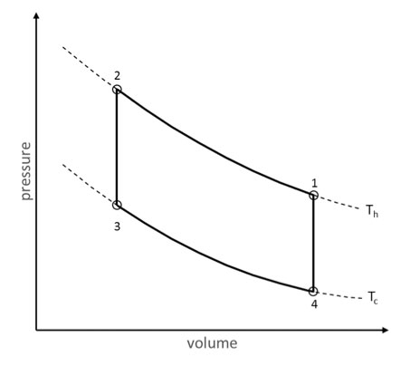
Ciclos Refrigeracion | PDF | Heat Pump | Air Conditioning The Ts diagram of the basic vapor heat pump cycle, which consists of the following four processes, is shown in Fig. 6.10: 1-2 2-3 3-4 4-1 Isentropic compression Isobaric cooling Throttling Isobaric Basic vapor heat pump TS diagram. Copyright 2004 by Marcel Dekker, Inc. All Rights Reserved. 33 Heat Pump Ts Diagram - Wiring Diagram Database The ts diagram shows an ideal double cascade system using the same refrigerant in each loop. A fair heat pump comparison of trane vs goodman within trane heat pump parts diagram image size 573 x 306 px and to view image details please click the image. Heil Heat Pump Wiring Diagram : Ts 0638 Ruud 80 Furnace Wiring... Diagnostic features of heat pump controller goodman heat pump wire colors thermostat wiring diagram on package. This diagram is to be used as reference for the low voltage control wiring of your heating and ac system. I have replacaed the two wire thermostate cable with a five wire cable.
Heat pump ts diagram. Complete Carnot Cycle, efficiency, PV diagram, TS diagram, Theorem 14. Carnot cycle TS diagram. As you know, thermodynamics is the branch of science which deals with the study of the conversion of heat energy into Example. The water does not move by itself from down to top. You need a water pump to continue this process. Reversible and Irreversible process. Heat Pump - an overview | ScienceDirect Topics Heat pumps use mechanical energy to transfer thermal energy from a source at a lower temperature to a sink Heat pumps may use air or water sources for energy, and dual-source machines that can use either are under °C. A simplified schematic flow diagram of the Zubadan heat pump is shown in Fig. T-S diagram of heat pump cycle[6]. T-s ... - ResearchGate T-s diagram of heat pump cycle is shown in figure 2. The low-pressure sub-cooled steam point 7 is compressed to point 1, which is an adiabatic compression. ... How to calculate work and heat change from a TS... - Quora Area under a curve in a TS diagram represents heat transfer involved in the process. The area under a TS diagram has units of energy. It represents a component of the Gibbs Free energy of that system. It may increase or decrease, whether the process is reversible or irreversible is irrelevant...
(a) Ph diagram and (b) Ts diagram of standard heat pump cycle. This paper proposes a quick method to investigate coefficient of performance (COP) of vapor compression heat pump from a dimensionless term, Figure of Merit ... Heat pump COP, part 2: Generalized COP estimation of heat ... (3) Fig. 1 depicts the pressure-enthalpy (p-h) and temperature-entropy (T-s) diagram of a generic heat pump process for an azeotropic refrigerant under sub-critical operation. The process shown in Fig. 1 represents a simple one-stage heat pump, the schematic of which may be seen in Fig. 2. 25 Heat Pump Ts Diagram - Wiring Database 2020 A temperatureentropy diagram or ts diagram is a thermodynamic diagram used in thermodynamics to visualize changes to temperature and A fair heat pump comparison of trane vs goodman within trane heat pump parts diagram image size 573 x 306 px and to view image details please click the image. An Investigation into Ground Source Heat Pump... | Manualzz Basic Thermodynamic Premise of a Heat Pump. Carnot Cycle on a Temperature-Entropy (TS) Diagram. Fig 5. Heat Pump Output Diagram for Different Source and Sink Temperatures [5]. Function Diagram of a Reversible Heat Pump in Cooling Mode [5].
Steam engine - Wikipedia A steam engine is a heat engine that performs mechanical work using steam as its working fluid.The steam engine uses the force produced by steam pressure to push a piston back and forth inside a cylinder. This pushing force can be transformed, by a connecting rod and crank, into rotational force for work.The term "steam engine" is generally applied only to reciprocating … Einstein refrigerator - Wikipedia The Einstein–Szilard or Einstein refrigerator is an absorption refrigerator which has no moving parts, operates at constant pressure, and requires only a heat source to operate. It was jointly invented in 1926 by Albert Einstein and his former student Leó Szilárd, who patented it in the U.S. on November 11, 1930 (U.S. Patent 1,781,541).The three working fluids in this design are water ... TS Diagram of a Generalized Irreversible Carnot Type ... A reverse Carnot cycle forms the basis of all heat-pump cycles in providing heating and cooling loads. The optimal exergy-based Ecological analysis of an ... T-s (temperature-entropy) diagram of irreversible heat ... Download scientific diagram | T-s (temperature-entropy) diagram of irreversible heat pump and refrigerators cycles (T H = high temperature, ...
Uncategorized
Calculating work heat, and efficiency given a TS diagram Homework Statement Is it possible to calculate the work done heat transfer, and efficiency of an object in a thermodynamic system, given the Temperature...

Carnot Cycle – pV, Ts diagram | Processes | nuclear-power.com
What are Different Types of Thermodynamic Cycles? (PDF) When the processes of cycles are outlined on the p-v diagram, they form a closed figure, each A machine which operates on a reversed cycle is considered as a "heat pump", for example, a this is amazing explanation and need this PDF ,Full notes on Stirling cycle with PV and TS diagram ,Full...

Evaluation of a single stage heat pump performance by figure ...
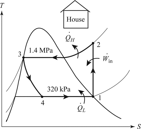
Schematic diagram of heat pump system Figure 2. T-s ... T-s diagram of heat pump system from publication: Energy an exergy analysis of ... Heat Pumps, Exergy Analysis and Exergy | ResearchGate, the professional ...
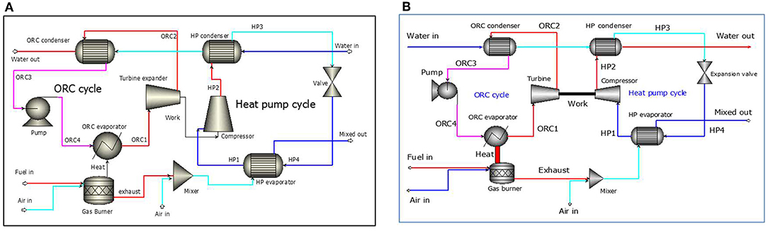
Frontiers | Design Strategies and Control Methods for a ...
The Do's & Don'ts of Hydronic System Design | PM Engineer Pump away from expansion tank. This has to be one of the most frequently emphasized details of modern hydronic heating. It still amazes me how it faded into This allows the controller to use the full range of stem lift as it varies heat output from 0 to 100%. > FIGURE 3. The Don'ts.
Engines and Heat Pumps - Revise.im
The T-S diagram of a theoretical heat pump cycle for: (a ... Heat pumps are currently considered as one of the most promising means for meeting low energy consumption requirements in buildings. ... The expansion process is regarded as being isenthalpic. The T-S diagrams of the cycles used for the pure fluid and the mixtures are shown in Fig.

File:T-s diagram specific heat.svg - Wikimedia Commons
Temperature Entropy (T-s) Diagram - Thermodynamics ... Temperature Entropy (T-s) Diagram - Thermodynamics. Thermodynamics Directory | Heat Transfer Directory. A T-s diagram is the type of diagram most frequently used to analyze energy transfer system cycles. This is because the work done by or on the system and the heat added to or removed...
Carnot cycle: p-V diagram and T-S diagram
T-s diagram for heat pump cycle. | Download Scientific Diagram T-s diagram for heat pump cycle. In natural gas distribution system, gas pressure is regulated correspond to requirement using throttle valve which is releasing huge pressure energy as useless ...

STEPS: Technology description
Re-circulating hot water without a pump - Charles Buell ... 29.11.2014 · heat pump uses 3-5 but makes the garage an ice box during the winter. there is no way to vent the cold air to the outside at this point, my main problem is the recirc loop, i’m a strong believer now that the return loop should be encased with the main trunk, hevily insulated and kept out of the foundation, leave it the attic.

a) Schematic illustration of the heat pump; (b) ideal T-S ...
Applications of Thermodynamics: Heat Pumps and Refrigerators Figure 2. Heat pumps, air conditioners, and refrigerators are heat engines operated backward. The one shown here is based on a Carnot (reversible) engine The directions of W, Qh, and Qc are opposite what they would be in a heat engine. (b) diagram for a Carnot cycle similar to that in Figure 3 but...
Solved) - Air within a piston-cylinder assembly executes a ...
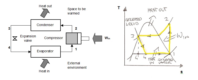
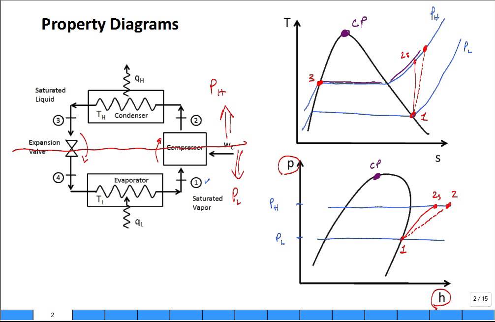
Heat Pumps Heat pumps are devices that operate in a cycle similar to the vapor-compression refrigerator cycle illustrated in Figure 1. In its most basic form, a vapor-compression refrigeration system [see Van Wylen (1985)] consists of an evaporator, a compressor, a condenser, a throttling device which is usually an...

40 HVAC ideas | hvac, refrigeration and air conditioning ...
Chapter 10 Refrigeration & Heat Pump Cycles (Systems) provides the heat input to the evaporator of a high-temperature cycle, e.g., 2 units in series • Normally a different refrigerant would be used in each separate cycle, in order to match the desired ranges of T & P. • The Ts diagram shows an ideal double-cascade system using the same refrigerant in each loop.
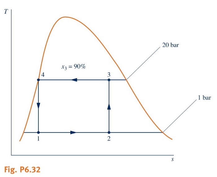
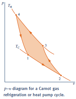
Solved 6.32 Figure P6.32 provides the T-s diagram of a ...
Heat Pumps Explained - The Engineering Mindset Learn how heat pumps work and the different types of heat pumps available. We cover the working principle of heat pumps and use animations to help They even built a heat pump website that has business cases, case stories, eLessons, and even a fun diagram similar to the ones you see on this...

Heat Engines
TS diagram of process of the cascade heat pump In this article is presented a thermodynamic analysis of a cascade heat pump system designed for using in high-temperature heating systems.
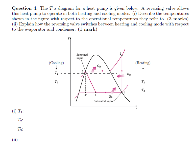
The T-s diagram for a heat pump is given below. A | Chegg.com
Temperature-entropy diagram - Wikipedia The classical Carnot heat engine. Category. v. t. e. A temperature-entropy diagram, or T-s diagram, is a thermodynamic diagram used in thermodynamics to visualize changes to temperature and specific entropy during a thermodynamic process or cycle as the graph of a curve.
RESCO Site Analysis Project
Heat Pumps Explained - How Heat Pumps Work HVAC - YouTube How heat pumps work, in this video we'll be discussing how heat pumps work starting from the basics to help you learn HVAC engineering. We cover Air to air...

How does a Refrigeration Cycle work? | What is Refrigeration?
PDF Exergy Analysis of a Solar Assisted Ground-Source (Geothermal) Heat... Keywords: Ground-source Heat Pump, Geothermal Energy, Greenhouse, Exergy, Heat Pump, Renewable Energy, Solar Energy, Sustainable A schematic diagram of the experimental set up is illustrated in Figure 1. This system mainly consists of three separate circuits: (i) the ground coupling...

T-S Diagram of a Generalized Irreversible Carnot Type Heat ...
Ammonia Heat Pump - Chemical... - Cheresources.com Community Ammonia Heat Pump - posted in Chemical Process Simulation: Dear Everyone, I am trying to model Ammonia Heat Pump in HYSYS with condensing You will probably find the TS diagram with the cycle superimposed. Also, take into account that a compression efficiency less than 100% (every real...

Performance and economic evaluation of a photovoltaic/thermal ...
TS diagram of the improved model heat pump cycle for ... Download scientific diagram | T-S diagram of the improved model heat pump cycle for R134a/R245fa (33/67) from publication: Assessment of refrigerant ...

T-S diagram of process of the cascade heat pump | Download ...
Solved The T-s diagram for a heat pump is given below. A ... The T-s diagram for a heat pump is given below. A reversing valve allows this heat pump to operate in both heating and cooling modes. (i) Describe the temperatures shown in the figure with respect to the operational temperatures they refer to.
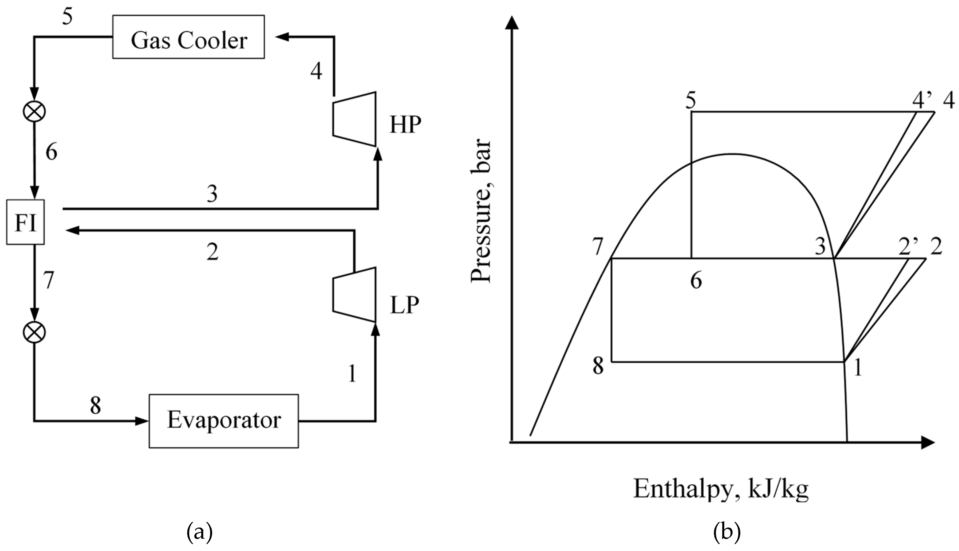
Energies | Free Full-Text | CO2 Refrigeration and Heat Pump ...
View 9 Heat Pump Cycle Ts Diagram - fanficisatkm53 Refrigerators and heat pumps; Coefficient of Performance; Refrigerator / Heat Pump Process Diagram; Clasius Statement. We Have got 6 pics about Heat Pump Cycle Ts Diagram images, photos, pictures, backgrounds, and more. In such page, we additionally have number of images out there.

Why Is Carnot Cycle Not Possible In Heat Pump And ...
PDF Problems and Solutions on Thermodynamics and Statistical Mechanics (b) Suppose that the heat pump is replaced by a simple heater which also consumes a constant power W and which converts this into heat with 100%efficiency. (a) Show a possible Carnot cycle on the TS diagram and describe in detail how the cycle is performed. (b) For your cycle, how much heat will be...
Vapor-compression refrigeration - Wikipedia
PDF Ground-source (geothermal) heat pumps Ground-source heat pumps, often referred to as geothermal heat pumps, overcome the problem of resource variations, as ground temperatures remain fairly constant throughout the year. Depending upon the soil type and moisture conditions, ground (and groundwater) temperatures experience little if...

Utilisation of Ambient Air and Shallow Geothermal Energy ...
Conventional Heat Pump - Jackson Systems T-32-TS... | ManualsLib Jackson Systems T-32-TS Manual Online: Conventional Heat Pump. When the T-32-TS is configured for conventional heat pump operation, testing is the same as a heating and cooling system with the exception that a 3 minute time delay is activated before the 'Y1' compressor relay will...

Performance optimization of regenerated Brayton heat pump ...
Ts Diagram Heat Pump Ts Diagram Heat Pump. Collections of Diagram Images With Details. Search anything about Diagram Ideas in this website. The coefficient of performance COP of reversible or irreversible refrigerator or heat pump is given by. This cycle is used to model the steam turbines.

1: T-s diagram of the reversed Rankine cycle of an air-water ...
PDF TS Diagram • Pumps - constant density compression. • Compressors - reversible ideal gas compression. ▪ Use of PH & TS diagrams ▪ Multistaging. Efficiencies. Isochoric Isenthalpic Adiabatic Isentropic (ideal reversible). constant temperature constant pressure constant volume constant enthalpy no heat...
Heat Engines
Otto Cycle - pV, Ts Diagram | Application | nuclear-power.com The temperature-entropy diagram (Ts diagram) in which the thermodynamic state is specified by a point on a graph with specific entropy (s) as the horizontal axis and absolute Ts diagrams are a useful and common tool, particularly because it helps to visualize the heat transfer during a process.

Carnot heat pump (or Carnot refrigerator)
Heil Heat Pump Wiring Diagram : Ts 0638 Ruud 80 Furnace Wiring... Diagnostic features of heat pump controller goodman heat pump wire colors thermostat wiring diagram on package. This diagram is to be used as reference for the low voltage control wiring of your heating and ac system. I have replacaed the two wire thermostate cable with a five wire cable.
Olvondo Technology | Make your energy green
33 Heat Pump Ts Diagram - Wiring Diagram Database The ts diagram shows an ideal double cascade system using the same refrigerant in each loop. A fair heat pump comparison of trane vs goodman within trane heat pump parts diagram image size 573 x 306 px and to view image details please click the image.
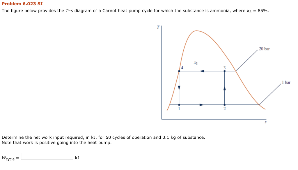
Solved Problem 6.023 SI The figure below provides the T-s ...
Ciclos Refrigeracion | PDF | Heat Pump | Air Conditioning The Ts diagram of the basic vapor heat pump cycle, which consists of the following four processes, is shown in Fig. 6.10: 1-2 2-3 3-4 4-1 Isentropic compression Isobaric cooling Throttling Isobaric Basic vapor heat pump TS diagram. Copyright 2004 by Marcel Dekker, Inc. All Rights Reserved.

Rankine cycle - Wikipedia
Use of the Lorenz Cycle in Heat Pumps | SpringerLink

TEMPERATURE ENTROPY DIAGRAM FOR WATER - UNDERSTANDING ...
Solved: A heat pump that operates on the ideal vapor ...

The T-s diagram is of a Carnot heat pump cycle for which the ...

Heat Engines Heat Pumps - ppt video online download

T-s diagram for heat pump cycle. | Download Scientific Diagram
![T-S diagram of heat pump cycle[6]. T-s diagram of heat pump ...](https://www.researchgate.net/publication/308674002/figure/fig2/AS:410943579279360@1474987992050/T-S-diagram-of-heat-pump-cycle6-T-s-diagram-of-heat-pump-cycle-is-shown-in-figure-2.png)
T-S diagram of heat pump cycle[6]. T-s diagram of heat pump ...
What is the T-s diagram for the Carnot refrigeration cycle ...

The T-S diagram of a theoretical heat pump cycle for: (a ...

Absorption heat pump cycles with NH3 – ionic liquid working ...
Where is the boiler and turbine on the T-s diagram of the ...
Property diagrams TS and PH for refrigeration 2
0 Response to "42 heat pump ts diagram"
Post a Comment