38 gas fireplace wiring diagram
Gas Fireplace Wiring Diagram For Your Needs Gas Fireplace Wiring Diagram Source: images.squarespace-cdn.com Read electrical wiring diagrams from unfavorable to positive plus redraw the signal like a straight collection. All circuits usually are the same ~ voltage, ground, single component, and buttons. User Guides & Manuals - Majestic Products User Guides & Manuals. User Guides & Manuals. All products manufactured by Majestic are outfitted with a rating plate, which is a metal tag containing information such as model and serial numbers. The rating plate is found in different places, depending on the unit: Gas Fireplaces and Gas Log Sets: The rating plate is near the gas control valve ...
Electric Fireplace Wiring Diagram - Studying Diagrams Gas fireplace wiring diagram - Exactly Whats Wiring Diagram. The temp sensor needs to have time to cool down in order to turn off the fan. In fact if our electric fireplace stove stops working due to an internal fault then theres nothing we can do about it except replace it. Assortment of electric fireplace wiring diagram.
Gas fireplace wiring diagram
GFK-160A Fan Kit NOTE: The factory installed junction box in the gas fireplace must be wired with 110 VAC before installing this kit. See Installation Instructions section. Installing the Fan Position the fan all the way to the rear and center in the fireplace. Pull the blower forward 1/8" to 1/4" from the back wall of the fireplace. See Figure 2. Thread fan cord plug through hole on bottom of cord bracket … Installation Manuals - Field Controls Installation Manual and Wiring Diagram for FSM Low Profile Series Millivolt Fireplace Damper. The Flue Sentinel® Millivolt Fireplace Damper is designed to operate with millivolt, standing pilot gas log replaces, and certain battery-powered spark ignition controls that operate on 3.3V battery supply. English. PDF Design Version - GFK4B Blower Kit with Timer Control ... NOTE: Diagrams and Illustrations NOT to Scale Page 4 of 6 My Fireplace Blower Burlington, Wisconsin 1-800-466-4045 MyFireplaceBlower.com: Ground Wire (Green) WIRING NOTES: This is a polarity sensitive system. Ensure you wire it exactly as shown in the diagram above. Thermopile wires must also be located with Red at TH/TP and White at TP on the ...
Gas fireplace wiring diagram. IFT-RC150 IntelliFire Touch Remote Control Installation ... figure 5. ift-rc150 wiring diagram flame sense igniter adapter s i 6 pin 6v dc battery pack red brn blk orange (pilot) green (main) blk ift-rc150 wireless wall switch rf module electronic control module ve (optional) wire assembly module reset switch appliance on/off control brn blk (optional on some models only) splitter blk red f. wiring diagram PDF FIREPLACE INSTALLATION - Comfortflame Blower Wiring Diagram CAUTION: Label all wires prior to disconnection when servicing controls. Wiring errors can cause improper and dan-gerous operation. Verify proper operation after servicing. FIREPLACE INSTALLATION Continued Figure 30 - Blower Wiring Diagram for Thermostat-Controlled Models Blue Variable Fan Switch Fan Switch (N.O.) Green ... Gas Fireplace Wiring Diagram Sample - Wiring Diagram Sample Wiring Diagram Pics Detail: Name: gas fireplace wiring diagram - Acucraft Custom Gas Circular Double Ring Fireplace Palomar Hotel Design Drawing 2. File Type: JPG. Source: acucraft.com. Size: 311.78 KB. Dimension: 2040 x 1320. PDF For Installers and Service Techni Cians Only Gas Fireplace ... Make sure all wiring is not damaged or broken and all connections are tight. Correct if necessary. By pas spill switch. If unit starts, replace spill switch. B-VENTED MODELS Check spill switch. Check to make sure the vent is drafting properly. Check for spillage. SEE PAGE 12. Make sure all venting meets manufactures specifications as well as ...
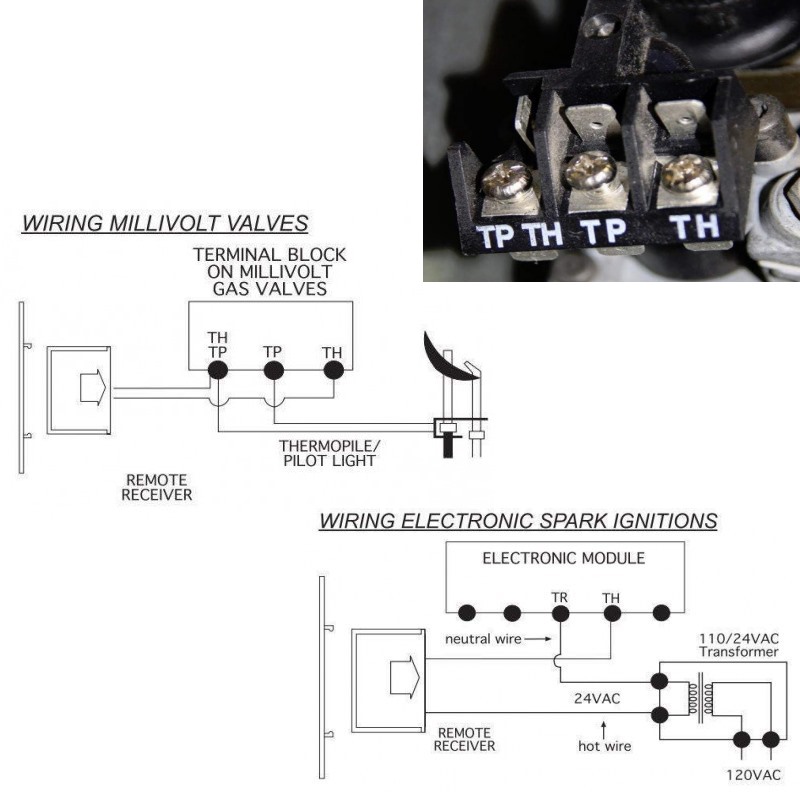
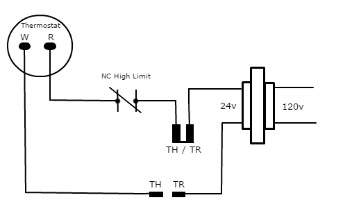
How to connect a Nest thermostat to a gas fireplace ... Wiring diagrams are included for the two most common types of ignition systems found in gas fireplaces. These ignition systems include the millivolt ignition (standing pilot / continuous pilot) and the intermittent pilot ignition IPI (electronic ignition). Wiring Diagram For Electric Fireplace Insert - Wire Assortment of gas fireplace wiring diagram. Wiring diagram for electric fireplace insert. Use appropriate wire to meet local and national. The temp sensor needs to have time to cool down in order to turn off the fan. If i turn the variable speed switch off and back on it will still the start fan motor. Frequently Asked Questions - Masterbuilt Can I use them in my fireplace or firepit? ... Can I use natural gas instead of propane for my gas smoker? No, Masterbuilt® smokers cannot be converted to natural gas. Our units are tested and designed to operate on LP gas and our company does not do any testing with natural gas. Therefore, we do not sell a natural gas conversion kit nor recommend the use of natural gas … Gas Fireplace Wiring Diagram - Studying Diagrams Gas Fireplace Wiring Diagram wiring diagram is a simplified up to standard pictorial representation of an electrical circuit. The following wiring diagrams are for illustration purpose only. There are lots to handle with this device and it can be quite difficult. The diagram shows 120v coming into a 120v24v transformer and.
INSTALLATION INSTRUCTIONS AND OWNER'S MANUAL INSTALLATION INSTRUCTIONS. AND. OWNER'S MANUAL. UNVENTED. GAS FIREPLACE. MODELS. VFD26FM(2,3)0(N,W,C)(N,P)-2. VFD26FP(2,3)0L(N,P)-2. VFD26FP70L(N,P)-1.44 pages Gas Fireplace Heater Manuals, Parts Lists, Wiring Diagrams ... Gas Fireplace & Gas Heater Manuals, parts lists, wiring diagrams: Free downloadable manuals for LP and natural gas-fueled gas fireplaces, gas logs, gas fireplace heaters. We include links to contact information for each manufacturer or producer of these heating products and their related equipment, parts, and installation, repair, wiring ... INSTALLATION & OPERATING INSTRUCTIONS Full View ... If the information in this manual is not followed exactly, a fire or explosion may result causing ... Mendota gas fireplaces are heat producing appliances.48 pages Wiring-Diagram-For-Ga-Fireplace - RAUR.US Wiring-Diagram-For-Ga-Fireplace. The diagram shows 120v coming into a 120v/24v transformer (and also into an outlet box where the fan kit plugs in to). Tighten the connections and check back if the fireplace works or not. Assets.regency-Fire.com from The wiring to the valve from the power supply is white wire to #2.
Owner's Manual
P48-1 Gas Fireplace Installation Manual 6 Regency P48-1 Zero Clearance Direct Vent Gas Fireplace INSTALLATION Diagram 1 UNIT SPECIFICATIONS This includes: 1) Clocking the appliance to ensure the correct firing rate (rate noted on label 51,000 (NG) Btu/h, 48,000 (LP) Btu/h) after burning ap-pliance for 15 minutes. 2) If required, adjusting the primary air to en-sure that the flame ...

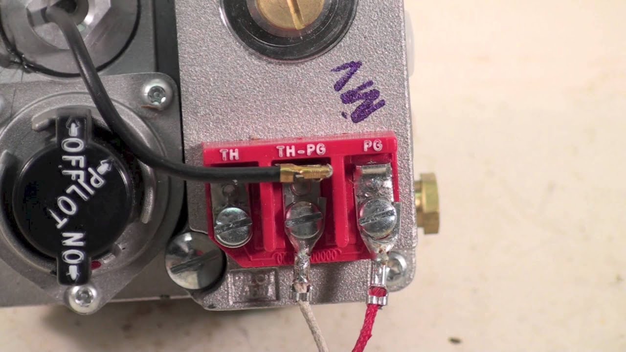
How to Test your Thermopile - www.mygasfireplacerepair.com
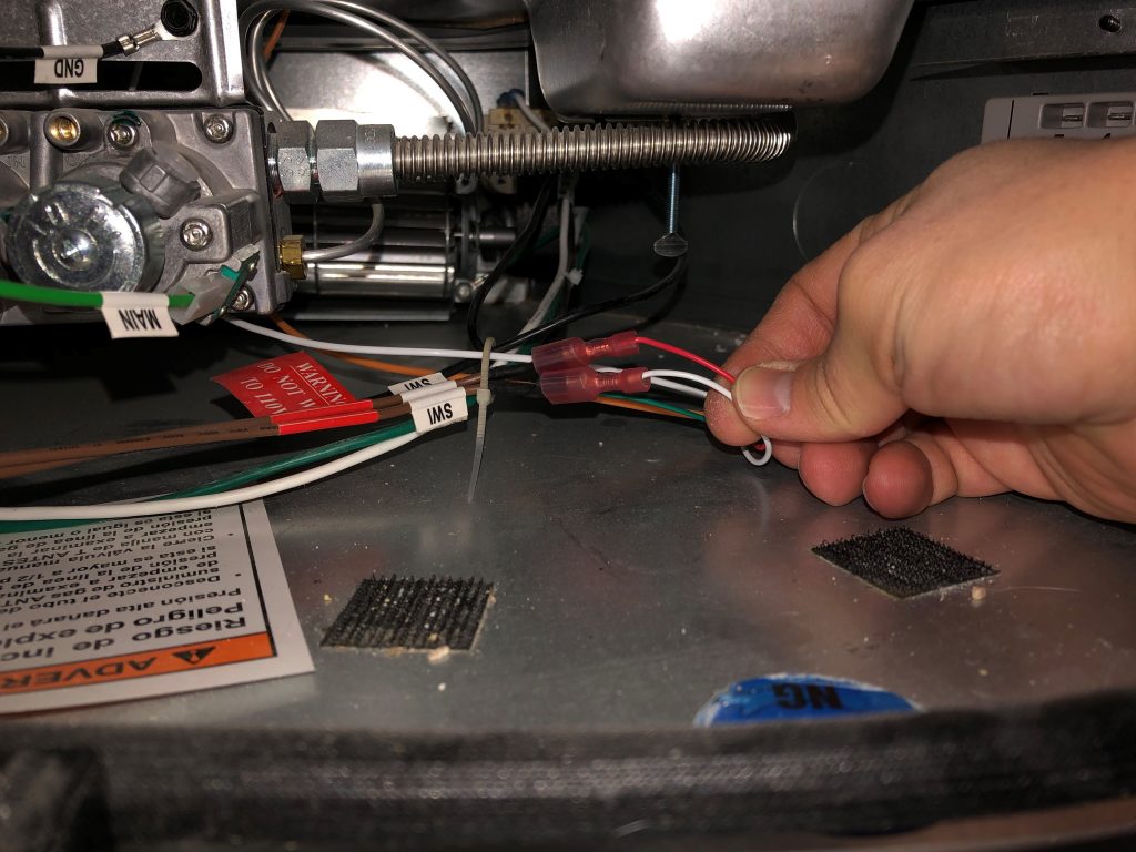
Off Topic: How to Automate Your Gas Fireplace - The Dataist Step 1: Connecting the Low Voltage Wiring. The first step is to open the bottom panel of your fireplace (mine is held on by magnets) and find the wiring which goes to the wall switch. If your installer did a good job, it will be labeled for you. If not, just look for small wires heading out of the fireplace up towards the switch.
What does trans, rem/aux, and fan mean on a junction box for ...
Heatilator Gas Fireplace Manual [Step By Step Guide] 18.05.2021 · 8 Steps To Install A Heatilator Gas Fireplace. Installing a Heatilator gas fireplace can be tricky. But here, it will surely get easy for you. You can rest assured that the method we are going to apply is totally authentic as we are relying on the Heatilator gas fireplace manual for the direction.
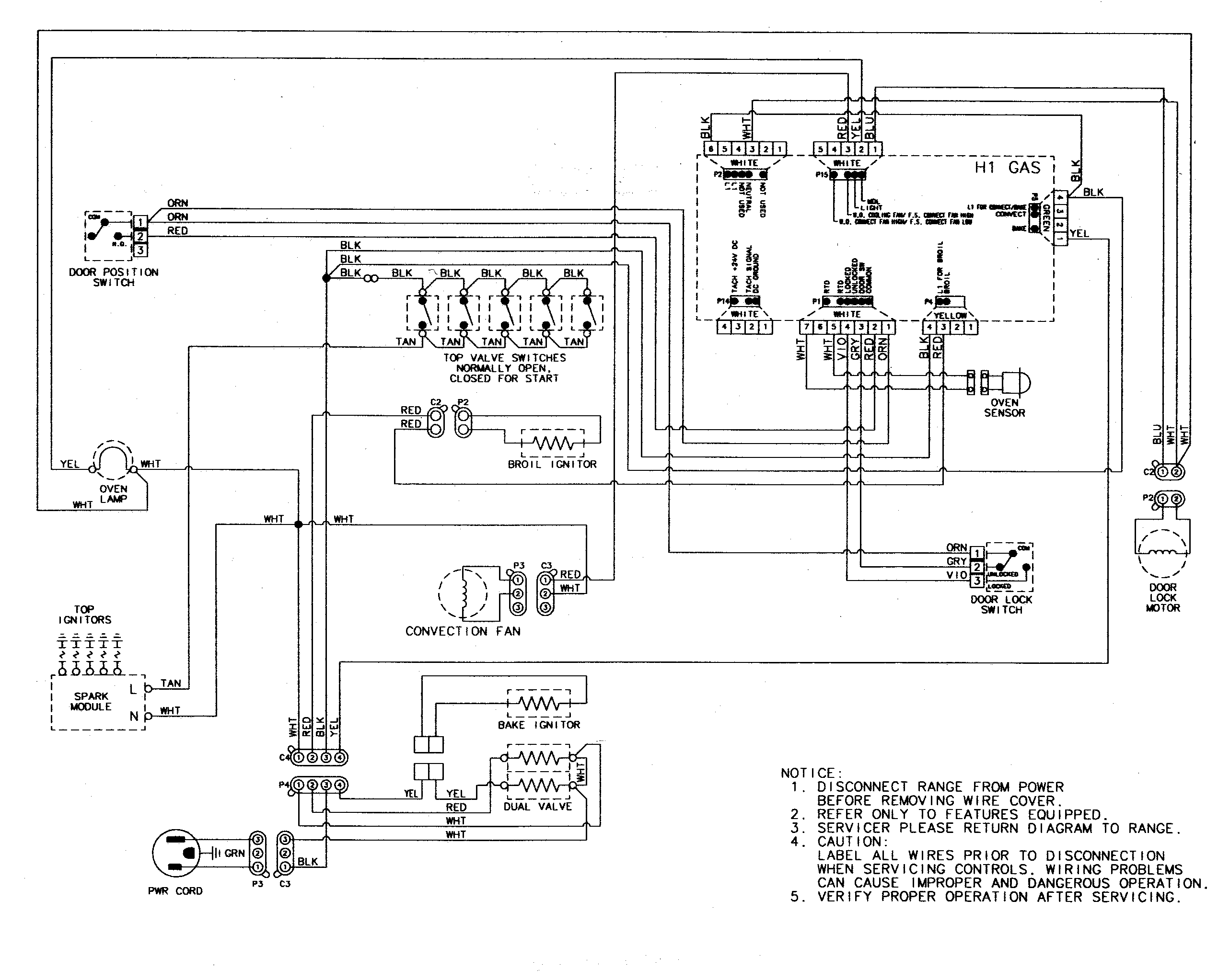
Amana AGR5835QDQ Freestanding Gas Range Timer - Stove Clocks ...
Gas Fireplace Wiring Diagram Gallery - Wiring Collection gas fireplace wiring diagram - Exactly What's Wiring Diagram? A wiring diagram is a kind of schematic which uses abstract pictorial signs to show all the interconnections of components in a system.

Gas Fireplace Wall Switch not Working: 3 Fixes - How to Air
Gas Fireplace Wiring Diagram | Eletricidade, Eletricista, Cat5 Gas Fireplace Wiring Diagram. Find this Pin and more on Electrical by M. Dimplex Electric Stove. Dimplex Electric Fireplace. Electric Fireplace Heater. Natural Gas Fireplace. Modern Fireplace. Baseboard Heater Thermostat. Contemporary Electric Fireplace.
Gas millivolt wiring
PDF Majestic Gas Fireplace Wiring Diagram Fireplaces Majestic Gas Fireplace Wiring Diagram Fireplaces is to hand in our digital library an online access to it is set as public hence you can download it instantly. Our digital library saves in combination countries, allowing you to acquire the most less latency period to download any of our books past this
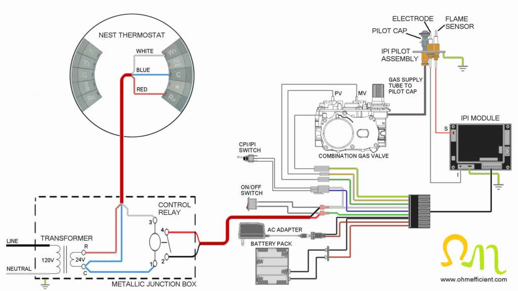
How to connect a Nest thermostat to a gas fireplace ...
Millivolt Gas Valve Wiring Diagram - schematron.org a gas valve, thermopile, millivolt thermostat, and a pilot Millivolt system wiring diagram.DEAN MILLIVOLT GAS FRYERS (NON-CE) CHAPTER 3: INSTALLATION INSTRUCTIONS Gas Conversion Procedures See gas valve illustration below and gas valve, burner and orifice location on page when performing the following conversions.
INSTALLATION AND OPERATING INSTRUCTIONS
4415 HO GSR2 - Travis Industries Fireplace Natural Gas or Propane Residential or Mobile Home This appliance may be installed in an aftermarket, permanently located, manufactured home (USA only) or mobile home, where not prohibited by local codes. This appliance is only for use with the type of gas indicated on the rating plate. A conversion kit is supplied with the appliance. INSTALLER: Leave this manual …

Gas fireplace malfunction - DoItYourself.com Community Forums
Princeton-Manual-10-09.pdf - Kozy Heat We welcome you as a new owner of a Kozy Heat gas fireplace. Kozy Heat ... Read this manual before installing or operating this appliance.80 pages
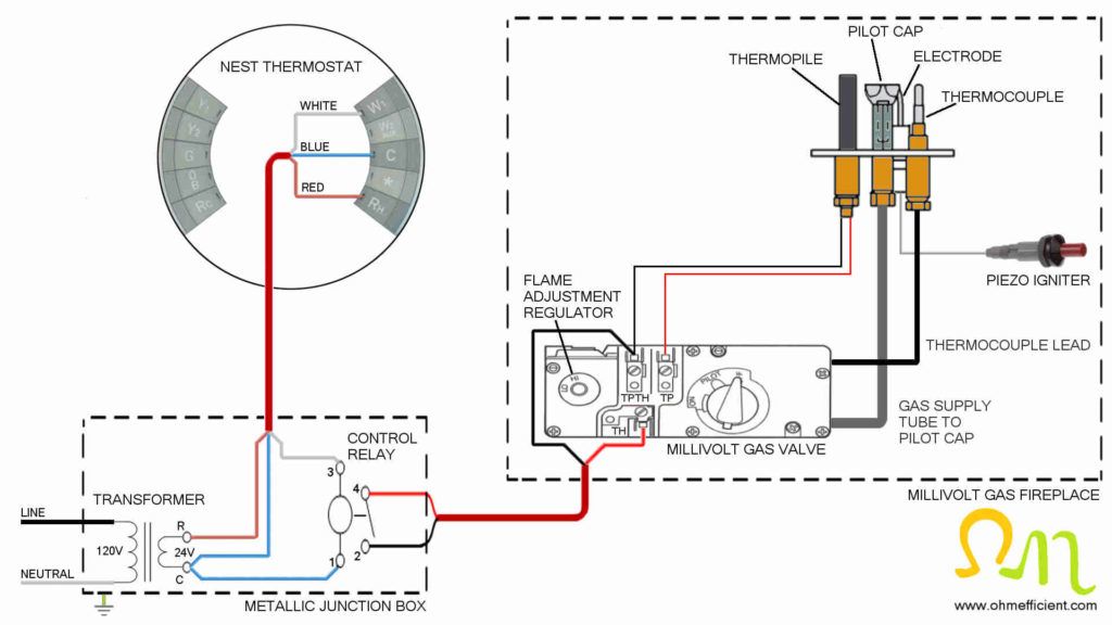
How to connect a Nest thermostat to a gas fireplace ...
Gas Fireplace Wiring Diagram - easywiring Gas fireplace wiring diagram. We include links to contact information for each manufacturer or producer of these heating products and their related equipment parts and installation repair wiring. It reveals the elements of the circuit as simplified shapes and the power and also signal connections between the devices. Acucraft mercial gas fireplace.
Smarten up Your Gas Fireplace This Winter | The Digital Media ...
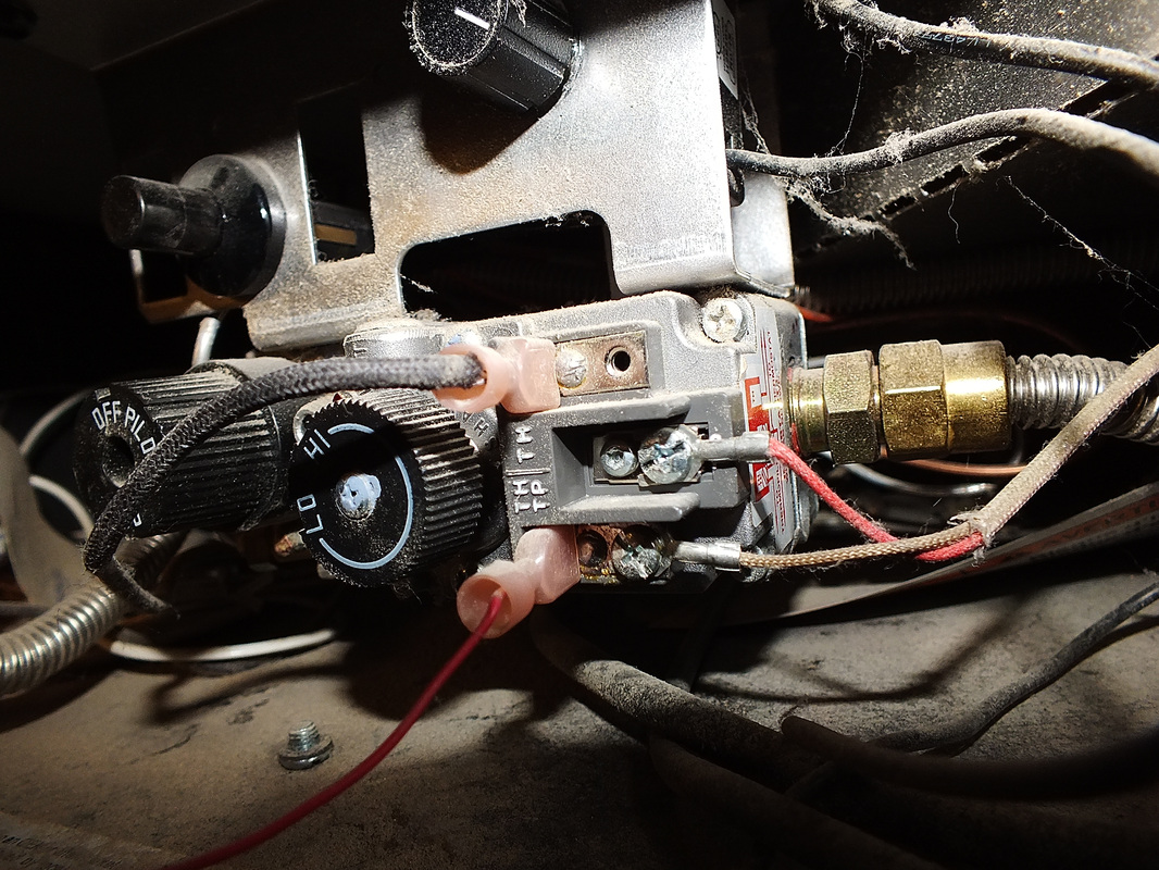
How the fireplace thermopile system is wired - YouTube This one covers the thermopile wiring on the gas fireplace. This video is part of the heating and cooling series of training videos made to accompany my web...
INSTALLATION DATA 710 SERIES LOW CAPACITY GAS HEATING CONTROLS
Amazon.com: Durablow Fireplace Electronic IPI Pilot ... It fits more newer fireplace models, please check your owner manual for part numbers or wiring diagram: ... Napoleon: Ascent 35 / 42 Direct Vent Gas Fireplace, B35 Ascent 35, BGD33, BGD34, BGD36, BGD36CF, BGD36CFG BGD36CFG-2 Crystallo, BGD40, BGD42, BGD42CF, GD19 Vittoria, GD34, GD36, GD36M, GD36MN Manhattan, GD70 STARfire Series (-1S & -2S), …

The Main Burner Flame Will Not Come On or Stay On - www ...
PDF Gas - Direct Vent Millivolt System 4 WS-415-106 /05.19.99 GENERAL INSTRUCTIONS THIS GAS FIREPLACE SHOULD BE INSTALLED AND SERVICED BY A QUALIFIED INSTALLER to conform with local codes. In absence of local codes, install to the current National Fuel Gas Code, ANSI Z223.1, or the current CAN/CGA B149,
Gas Controls
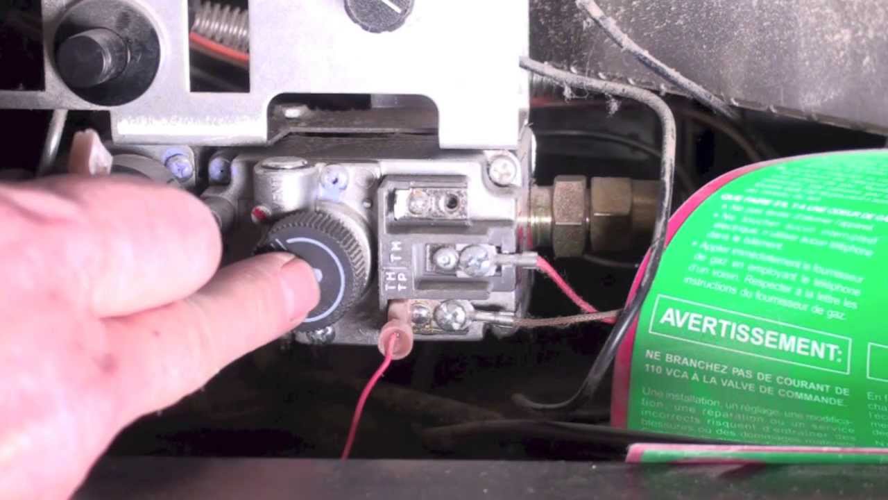
750 Millivolt Gas Valve, Thermopile Wiring & Wiring Diagram! This is How to Wire the Thermopile to The 750mv Gas Valve for the Pilot and Main Gas Burners. This includes a WIRING DIAGRAM. I show you how to Light the Pil...
You may be trying to access this site from a secured browser on ...
Buck Stove Wiring Diagram Buck Stove Model 32 Gas Heater pdf manual download. Also for: Fp Buck stove model If so, see Figure 2, page 11 for wiring diagram. MANUAL LIGHTING PROCEDURE If the pilot cannot be lit with the piezo, it can be manually lit with the use of a paper match and a lighter. Assortment of buck stove blower wiring diagram.

Napoleon Fireplaces Support
Owner's Manual - Hearth & Home Technologies Your new Hearth & Home Technologies gas fireplace will give you years of durable use and ... Read this manual before installing or operating this appliance.43 pages
INSTALLATION DATA 710 SERIES LOW CAPACITY GAS HEATING CONTROLS
PDF Gas Fireplace Wiring Diagram - api.smallplanet.com gas-fireplace-wiring-diagram 1/1 Downloaded from api.smallplanet.com on April 5, 2022 by guest Recognizing the pretension ways to get this books Gas Fireplace Wiring Diagram is additionally useful. You have remained in right site to begin getting this info. acquire the Gas Fireplace Wiring Diagram associate that we present here and check out ...

Installation, Wiring diagrams, Natural gas | Regency Zero ...
PDF MILLIVOLT SYSTEM - Napoleon® | Grills, Fireplaces ... 4 WS-415-137 / 05.15.00 GENERAL INSTRUCTIONS THIS GAS FIREPLACE SHOULD BE INSTALLED AND SERVICED BY A QUALIFIED INST ALLER to conform with local codes. In absence of local codes, install the GB20 to the current National Fuel Gas Code, ANSI Z223.1, or the

Help wiring fireplace fan and 2 heat runs. - DoItYourself.com ...
Welcome to the Largest Fireplace Replacement Parts Store ... Gas Fireplace Replacement parts for all major brands of Gas fireplaces. All Parts in stock and ready to ship.

GFK-160A Blower Fan Kit for Majestic Direct Vent Fireplaces
Heat & Glo Fireplace Manuals | Heat & Glo 8000 Series Gas Fireplace UL Listing: Install Manual 6000/8000CBV-IPI. 6000TVFL/8000TVFL/SL-36TV French. 6000XLS/GDFVL 8000GDVFL. 8000TRD. 8000TVD. 6000/8000CLX-IPI-T/S -IPILP-T/S Spanish. 6000C/8000C & IPI Latin American Spanish. 6000CL/8000CL-IPI-T & -S Latin American Spanish ...
How the fireplace thermopile system is wired
SPK-500 | Southern Pride BBQ Pits & Smokers Features. List Price: U.S., Canada & Mexico $24,739 + tax and freight List Price: 120v International $24,739 + tax and freight List Price: 230v International $28,704 + tax and freight Convection air system. The 75,000 BTU (22KW) burner heats the smoker cabinet and ignites the 2-3 fireplace size logs in the firebox to obtain the desired flavor, aroma, and texture.
Skytech 5301 On/Off/Thermostat/Timer Touch Screen Fireplace Remote Control
PDF Installation Instructions Manual | FBK250 | Fireplace ... •Wiring Diagram for this Blower Kit is illustrated in Figure: 7. Blower operates on 120V/60Hz power. Figure: 8 CLICK CLICK CLICK Finishing Steps: If appliance is connected to a gas supply, turn it back on. If Appliance is connected to 120 Volt Power, turn it back on. Installer is responsible to check local codes

Fireplace Remote Control – Fireplace Blower Outlet
Energy E21 Gas Insert Owners & Installation Manual Regency® E21-10 Gas Fireplace Insert | 3 installation |3 Shown with Low Profile Faceplate Oversize Faceplate Dimensions: 44-1/8" W x 25-3/4" H ALL PICTURES / DIAGRAMS SHOWN THROUGHOUT THIS MANUAL ARE FOR ILLUSTRATION PURPOSES ONLY. ACTUAL PRODUCT MAY VARY DUE TO PRODUCT ENHANCEMENTS.

Robertshaw gas valve wiring help | The Garage Journal
SIT Proflame II (GTMF) System Intermittent Pilot Ignition ... Wiring Diagram Pg 19. 2 System Overview: The primary components that are included in the SIT Proflame II GTMFS System Gas Valve Integrated Fireplace Control (IFC) SIT Pilot Assembly Transmitter (remote control) (GTMF model) 3 Solenoids on Valve: EV1 (Pilot Connection Coil): Opens and closes to release gas to the pilot Orange in color furthest from step motor 5VDC …
36DV OWNER'S MANUAL
Wiring a gas fireplace - Ask Me Help Desk The wiring diagram is very unclear as to how to install this unit. Here's my interpretation: The diagram shows 120v coming into a 120v/24v transformer (and also into an outlet box where the fan kit plugs in to). The transformer then has three low voltage wires coming from it to the millivolt gas valve.
Installation Instructions Manual | FBK250 | Fireplace Blower Kit
PDF Design Version - GFK4B Blower Kit with Timer Control ... NOTE: Diagrams and Illustrations NOT to Scale Page 4 of 6 My Fireplace Blower Burlington, Wisconsin 1-800-466-4045 MyFireplaceBlower.com: Ground Wire (Green) WIRING NOTES: This is a polarity sensitive system. Ensure you wire it exactly as shown in the diagram above. Thermopile wires must also be located with Red at TH/TP and White at TP on the ...
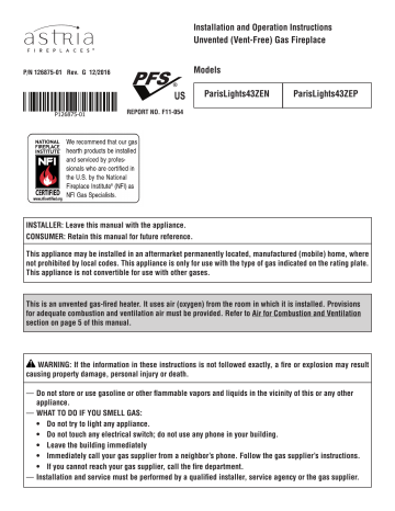
Installation and Operation Manual - Astria Fireplaces ...
Installation Manuals - Field Controls Installation Manual and Wiring Diagram for FSM Low Profile Series Millivolt Fireplace Damper. The Flue Sentinel® Millivolt Fireplace Damper is designed to operate with millivolt, standing pilot gas log replaces, and certain battery-powered spark ignition controls that operate on 3.3V battery supply. English.

Alexa Fireplace - Switch Wiring Diagram (companion video)
GFK-160A Fan Kit NOTE: The factory installed junction box in the gas fireplace must be wired with 110 VAC before installing this kit. See Installation Instructions section. Installing the Fan Position the fan all the way to the rear and center in the fireplace. Pull the blower forward 1/8" to 1/4" from the back wall of the fireplace. See Figure 2. Thread fan cord plug through hole on bottom of cord bracket …
Regency HZO42 Outdoor Gas Fireplace
Fireplace blower installation | DIY Home Improvement Forum
A2-019 APK-11 Instructions.indb
Gas Fireplace Resources - Perfection Supply
Gas fireplace millivolt systems - Gray Furnaceman Furnace ...

Installation, Wiring diagram, Aeration adjustment | Regency ...

Heatilator Electronic Ignition Natural Gas Fireplace Model ...

Repairing Your Fireplace Yourself Is Easier Than You Think ...

Lovely Wiring Diagram Gas Furnace #diagrams #digramssample ...
TH, TR, and TH/TR Gas Valve Terminals - HVAC School
0 Response to "38 gas fireplace wiring diagram"
Post a Comment