39 ammonia production process flow diagram
Process Flow Diagram of A HALDOR TOPSOE Process Ammonia ... The Ammonia synthesis process takes place in the ammonia converter according to the following reaction scheme. 2H2 + N2 = 2NH3 + Heat. The reaction is reversible and only part of hydrogen and nitrogen is converted to ammonia when the gas passes through the catalyst bed. Ammonia production - Wikipedia Block flow diagram of the ammonia synthesis process. Today, most ammonia is produced on a large scale by the Haber process with capacities of up to 3,300 tonnes per day. In this process, N 2 and H 2 gases are allowed to react at pressures of 200 bar. Ammonia is also processed by coal.
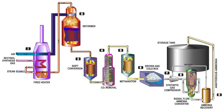
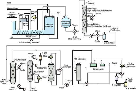
Ammonia Production | Encyclopedia MDPI Figure 1 shows the schematic diagram of conventional ammonia production from natural gas. The system consists of different processes: steam reformation, the water-gas shift reaction, CO 2 removal, syngas purification, and ammonia synthesis and separation.
Ammonia production process flow diagram
PDF The Catalyst Group Resources impacts of any/all gains in process improvements (integration, product yield, etc.); notably, ammonia is included among products in the top 18 (actually, it is #1) chemicals produced with 2.5 EJ of energy and 350 MT CO2/eq. The technology for ammonia production is mature and well-established, with only limited (PDF) Chemical Plant Design for the Production of Ammonia ... Figure 8: Simulated Process Flow Diagram for the Ammonia Production (Isometric View) Figure 9: Simulated Process Flow Diagra m (with labels) for the Ammonia Production 3.4 The economic analysis of ... PDF Petroleum Coke Gasification Based Ammonia Plant - IFFCO Initial ammonia production began in late 2000. The facility was built and initially operated by Farmland Industries, Inc. In March of 2004, the facility was sold to an investment group and named Coffeyville Resources. Process Description [see block flow diagram, fig-ure 1] Petroleum coke is received by truck from Coffey-ville Resources Refining ...
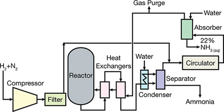
Ammonia production process flow diagram. Simulation of Ammonia Production using HYSYS Software - IISTE Fig (15) shows the Process Flow Diagram (PFD) for the production of ammonia process, generated by Aspen HYSYS. 2.3.1 Selection of components list: In this simulation, the reactant component list contain CH 4, H 2O, CO, CO 2, N 2, H2, O 2 ignoring sulfur content as the components for the ammonia production. PDF Demonstration and optimization of Green Ammonia production ... process, 4.0% Agriculture, 1.4% Waste , ... uPV-based green ammonia production meets the needs of ammonia in areas far from the ammonia supply chain. uLow-cost renewable power and cost reduction of electrolyzeris essential to reduce ammonia production cost. on Thank you for your attention AMMONIA PRODUCTION PROCESS AND FLOW SHEET IN ... - YouTube ammonia and flow sheet in hindi urea production process - for watching this videolike share comment... Haber's Process for the Manufacture of Ammonia & Its Uses The Haber process is typically carried out at pressures between 200 and 400 atmospheres and temperature of 500 o C. In the commercial production of ammonia, NH3 is continuously removed as it is produced. Removing the products causes more nitrogen and hydrogen to combine according to Le Chatelier's principle. The reaction is a reversible reaction.
Ammonia plant flowsheets - SlideShare 1. Ammonia Basic Flowsheet Elements. 2. Chemistry of the Ammonia Process. 3. Simplified Block Diagram of a Typical 1000 t/d Ammonia Plant. 4. Simplified Block Diagram of a 2000 MTPD Methanol Flowsheet Methanol Purification Reforming Compression Distillation Synthesis Steam Raising Feedstock (CH ) 4 Water VHT-S103 20 m³ VSG-EZ200 VSG-Z101 40 ... Introduction to Ammonia Production - AIChE Ammonia production has become one of the most important industries in the world. Without the crop yield made possible by ammonia-based fertilizers and chemicals, the global population would be at least two to three billion less than it is today (3).Ammonia production has increased steadily since 1946 (), and it is estimated that the annual production of ammonia is worth more than $100 billion ... Ammonia production flow diagram - Big Chemical Encyclopedia Ammonia production flow diagram Using the data given below, draw an information flow diagram of the process and calculate the process stream flow-rates and compositions for the production of 600 t/d ammonia. Use either the Nagiev split fraction method, with any suitable spreadsheet or manual calculations. [Pg.192] HALDOR TOPSOE AMMONIA PROCESS PDF - Cclap Process Flow Diagram of a HALDOR TOPSOE process Ammonia plant - Free download as Powerpoint Presentation .ppt), PDF File .pdf), Text File .txt) or view. Ammonia production process from natural gas with Catalyst, Temperature, pressure and composition at various points involved in the process.
PDF Introduction to Ammonia Production - AIChE the total annual production of synthesized ammonia was just over 300,000 m.t. Thanks to chemical engineering break-throughs, one modern ammonia plant can produce more than 750,000 m.t./yr. Approximately 88% of ammonia made annually is con-sumed in the manufacturing of fertilizer. Most of the remain-der goes into the production of formaldehyde. Ammonia Process Flow Diagram - Reactor Design - Beyond ... Ammonia Process Flow Diagram. Figure 4. Compressors with interstage cooling. (Used with permission of Simulation Sciences Inc.) excess of 21 bar are required to achieve sufficient conversion. Conversions of 20%-25% ammonia per pass are achieved. However, the conversion of hydrogen per pass is still less than 30%, therefore, the process requires ... The flow diagram showed the process required to produce ... The flow diagram showed the process required to produce 50,000 MT/yr. of ammonia through Haber process that generally manufactured industrially. The reaction is reversible; N 2 +3H 2 ↔ 2NH 3 and the process is exothermic reaction where the temperature will drop until it becomes the liquid product. The process followed the stoichiometry proportion which three moles of nitrogen present ... (PDF) KBR Ammonia | Manaf Satria - Academia.edu The first plant was the and as expected from the process flow diagrams CNOOC(1) ammonia plant, which was commissioned in September 2003. Compared to The "measured" values were calculated from the previous Purifier plant designs, the BFPL & performance test.
Introduction to Ammonia Production | AIChE
PDF Ammonia Synthesis for Fertilizer Production : Ammonia Production Process Flow Diagram 16 The Haber-Bosch process has remained the most common industrial method of ammonia manufacturing since its development, and though the most common commercial fertilizers contain ammonium sulfate, ammonium phosphate and urea as ingredients, these chemicals are all converted industrially from ammonia.
.jpg)
Ammonia
(DOC) UREA FLOW DIAGRAM | aakash puri - Academia.edu Aakash Puri. UREA FLOW DIAGRAM-: Flow Diagram of Urea Production Process from Ammonia and Carbon-dioxide Urea is manufactured by reacting ammonia and carbon dioxide in autoclave to form ammonium carbamate. The operating temperature is 135 oC and 35 atm pressure, the chemical reaction is endothermic reaction and so ammonia is maintained in ...

A flow diagram summarising the manufacture of ammonia from ...
Ammonia production - SlideShare Ammonia Production Following Steps are involved in the Production of Ammonia 1. Preparing PFD and BFD 2. Plant Designing 3. Modeling And Simulation 6. PFDs And BFDs Process Flow Diagram A process flow diagram (PFD) is a diagram commonly used in chemical and process engineering to indicate the general flow of plant processes and equipment.

Process flow diagram for the ammonia plant. | Download ...
Answered: onsider the block flow diagram of an… | bartleby Engineering Chemical Engineering Q&A Library onsider the block flow diagram of an ammonia (NH3) production plant shown below. The fresh feed to the process consists 30 mol% nitrogen (N2) and 70 mol% hydrogen (H2) that is fed at a rate of 100 kmol/h. The fresh feed is mixed with a cycle stream before entering the reactor.
Ammonia plant flowsheets
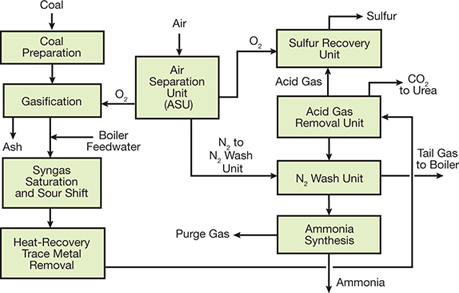
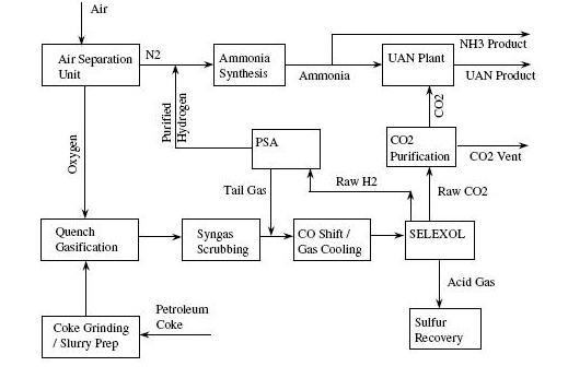
Ammonia Production Process Flow Diagram - Summarized by ... Ammonia and Urea Synthesis Figure 1 shows simplified BFD of Farmland Coke - to - Ammonia plant, to illustrate the typical flow scheme of gasification - base Ammonia and Urea production process. All component technologies are extensively, commercially proven. Per Figure 5, high purity H 2 is produced from Coke gasification.
11.1. Commercial Technologies | netl.doe.gov
Ammonia Production Process Flow Diagram - ppt making ... Ammonia Production Process Flow Diagram - 18 images - metric tons, flow diagram of urea production process from ammonia and, ammonia production process flow diagram images frompo, don t let it go to waste opra gas turbine,

Membrane reactors for ammonia production - ScienceDirect
ammonia production block flow diagram - windbornestudios Flow diagrams ( ammonia production block flow diagram ) Features • Chemical processes are represented as a connected of... As `` steam reforming, biomass gasification, and PV electrolysis process will produce gas synthesis to reacted. Possible by Using renewable energy to generate renewable ammonia from natural gas and ammonia July 5, 2011 module.

Engineers Guide: Block diagram of ammonia production and ...
Ammonia | NH3 | Process | Catalyst | Technology - Topsoe The low restriction on the process air obtained with the patented FreeBurn™ for secondary reformers will increase your ammonia production, if the process air capacity is a bottleneck. Alternatively, maintain the ammonia production and yield compression energy savings in your process air compressor.

Synthesis of Ammonia: Process & Reaction Video
Simplified process flow diagram of the benchmark ammonia ... Download scientific diagram | Simplified process flow diagram of the benchmark ammonia production plant. from publication: Cost-effective clean ammonia production using membrane-assisted ...

Plasma catalytic ammonia synthesis: state of the art and ...
PDF 8.1-2 Emission Factors 7/93 - Us Epa or the electrolysis of brine at chlorine plants. In the U. S., about 98 percent of synthetic ammonia is produced by catalytic steam reforming of natural gas. Figure 8.1-1 shows a general process flow diagram of a typical ammonia plant. Six process steps are required to produce synthetic ammonia using the catalytic steam reforming
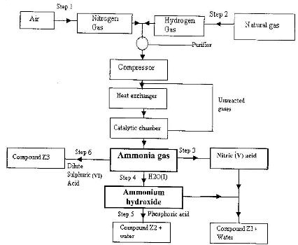
The flow chart below shows the industrial preparation of ...
PDF Modular Ammonia Production Plant - Events the ammonia synthesis reactor, see the Process Flow Diagram and Material Balance section above. The required hydrogen gas flow rate was used to design the size of each modular electrolysis cell system and find the required amount of electrical energy for the steady-state process.
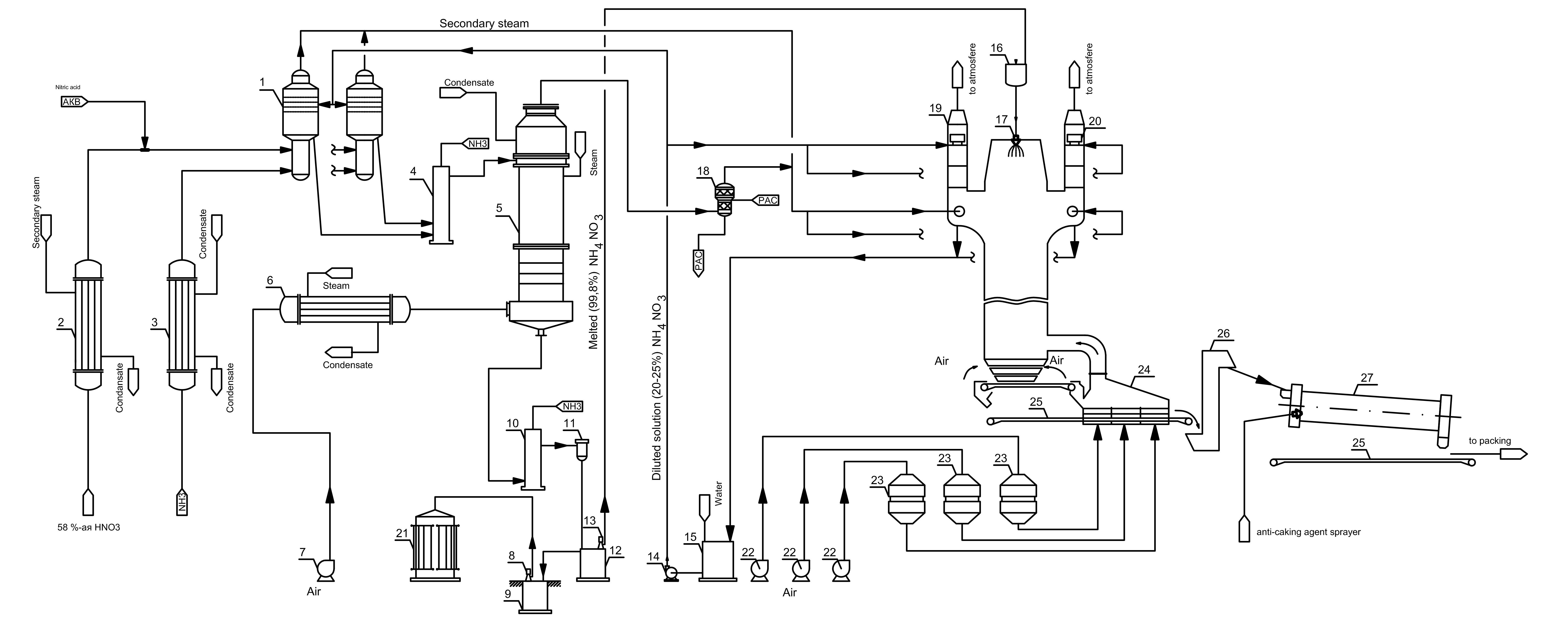
Ammonium Nitrate Technologies
PDF Petroleum Coke Gasification Based Ammonia Plant - IFFCO Initial ammonia production began in late 2000. The facility was built and initially operated by Farmland Industries, Inc. In March of 2004, the facility was sold to an investment group and named Coffeyville Resources. Process Description [see block flow diagram, fig-ure 1] Petroleum coke is received by truck from Coffey-ville Resources Refining ...

Ammonia Process Flow Diagram - Reactor Design - Beyond Discovery
(PDF) Chemical Plant Design for the Production of Ammonia ... Figure 8: Simulated Process Flow Diagram for the Ammonia Production (Isometric View) Figure 9: Simulated Process Flow Diagra m (with labels) for the Ammonia Production 3.4 The economic analysis of ...

Technologies-Ammonium nitrate-AMNIT process-EN
PDF The Catalyst Group Resources impacts of any/all gains in process improvements (integration, product yield, etc.); notably, ammonia is included among products in the top 18 (actually, it is #1) chemicals produced with 2.5 EJ of energy and 350 MT CO2/eq. The technology for ammonia production is mature and well-established, with only limited
Ammonia process - Dakota Gasification Company
Introduction to Ammonia Production | AIChE
Hydrogen via reforming aqueous ammonia and biomethane co ...

Figure 1 from Fabrication of Construction Materials in Urea ...

Petrochemical / Chemical Industry | MOGAS
Ammonia Synthesis for Fertilizer Production

Afbeeldingsresultaat voor process flow diagram ammonia plant ...

Simulation of Methanol and Urea Production from Catalytic ...
Introduction to Ammonia Production | AIChE
Chemical Plant Design for the Production of Ammonia through ...

Ammonia | Linde Engineering

Get Answer) - Figure 2-1 presents a qualitative flow diagram ...

eXe
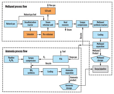
Process design overview for upgrading a gas-to-methanol facility
Process Flow Diagram - Types Of Process Flow Diagram With ...

Innovative Revamping of Ammonia plants for Capacity up and ...

Hydrogen cyanide – HCN – Manufacturing process for Hydrogen ...

Chemicals Manufacturing - Example Chemical Process Flow ...

AMMONIA PRODUCTION.avi - YouTube

PDF) Process Flow Diagram for Production of nitric acid and ...

Ammonia plant process flow diagram of single train section ...

Multi‐objective optimization of green urea production ...
.jpg)
Ammonia Production Control

Ammonia Process Flow Diagram - Reactor Design - Beyond Discovery

Absorbent-enhanced ammonia synthesis process flow diagram ...
0 Response to "39 ammonia production process flow diagram"
Post a Comment