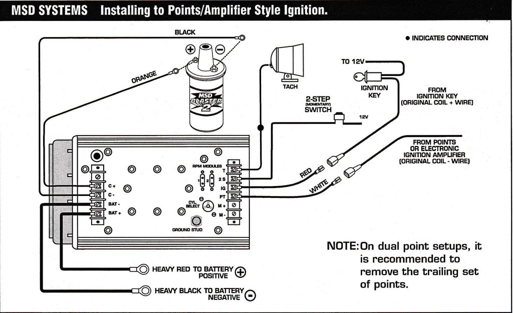
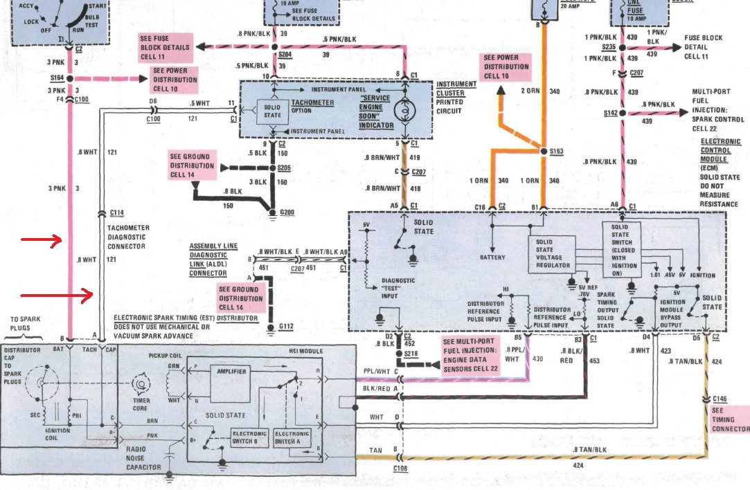
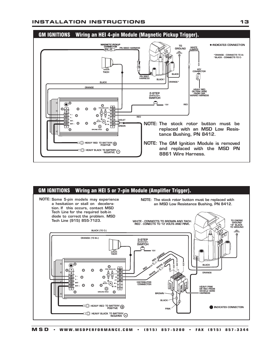
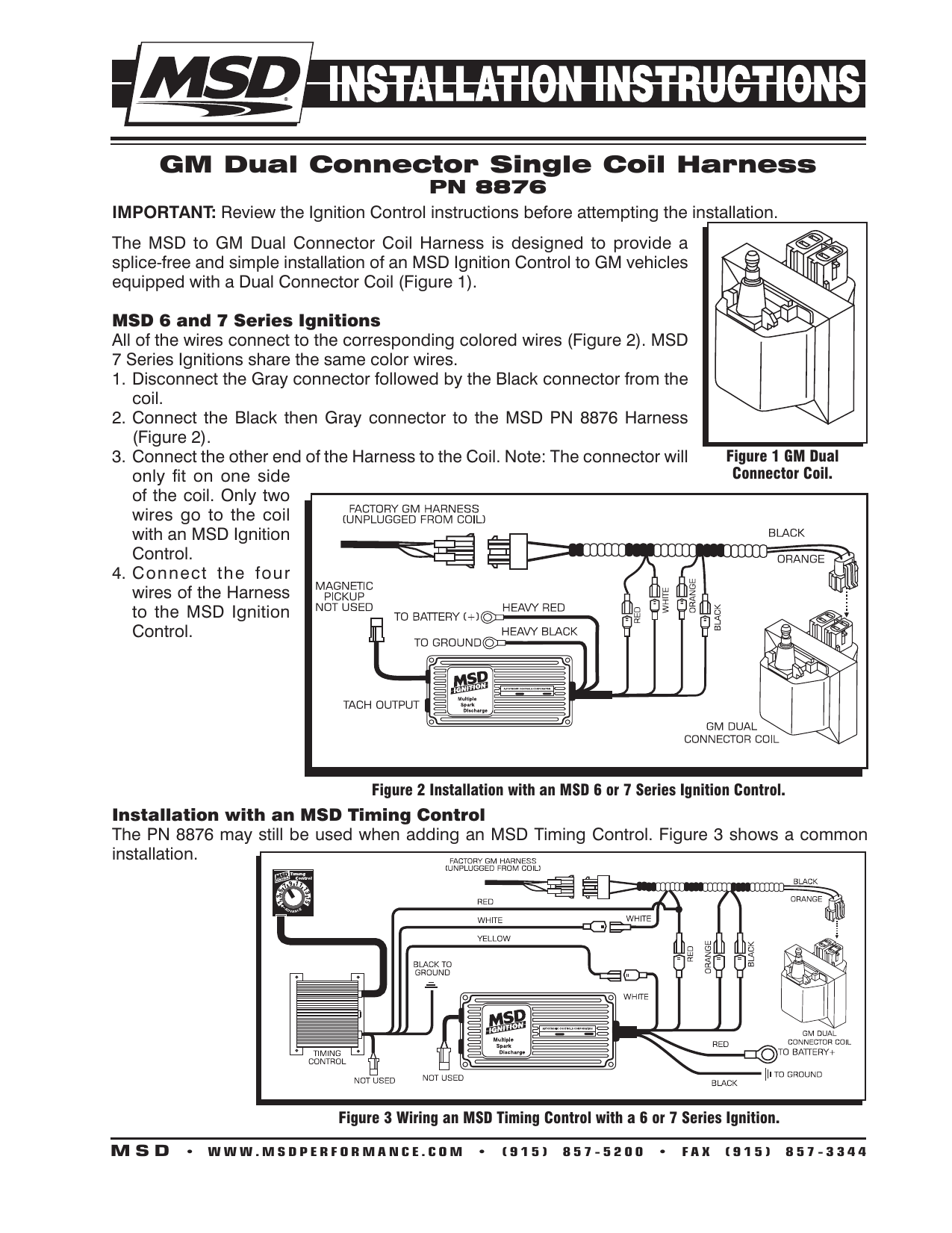
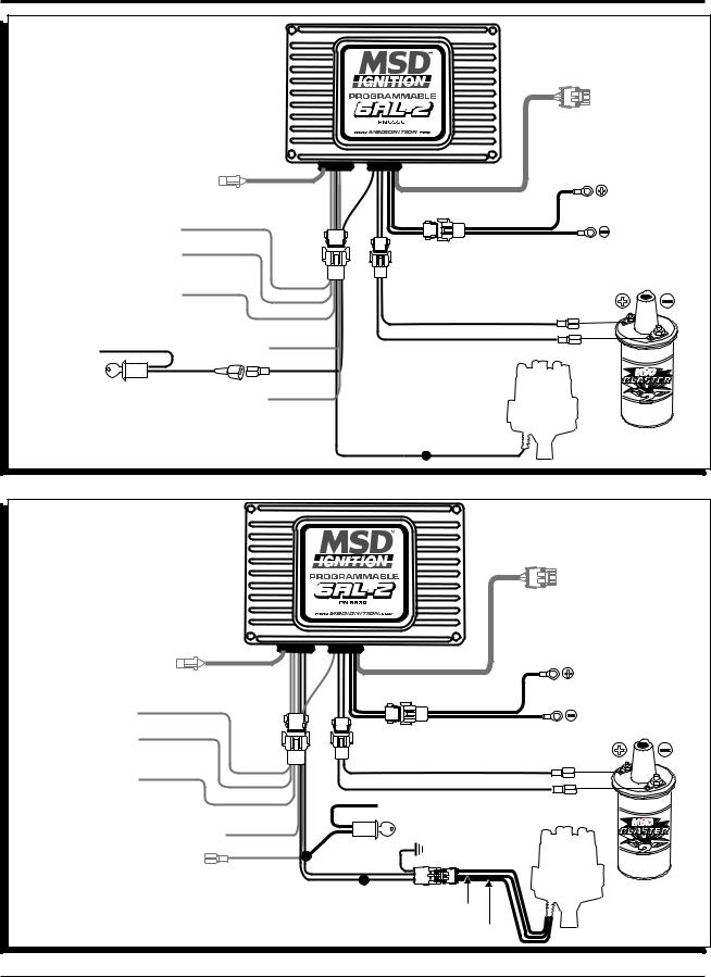
40 msd 7al2 wiring diagram
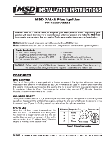
Msd 7al 2 Wiring Diagram - schematron.org Nov 25, 2018 · wiring diagrams and tech notes - MPS Racing. 1 - MSD 7AL-2 Plus Ignition. 1 - White Wire. 1 - Mag Pickup Extension Harness, PN 1 - Red Wire. 1 - Mag Pickup Adapter Harness, PN 4 - Vibration Mounts and Hardware. 1 - Coil Harness, PN 4 - RPM Modules: 3K, 7K, 8K and 9K. FEATURES. RPM LIMITERS. msd 7al wiring diagram - Wiring Diagram Msd 7al 2 Ignition Pn 7220 7224 7226 Pdf Free. Wiring Diagrams And Tech Notes Manualzz. Msd 7al 3 Ignition Control. Msd 7230 Ignition Kit Installation Instructions 121. Msd 7222 7al 2 Ignition Control Installation User Manual Page 14 16. Msd 7al 2 Ignition Pn 7220 7224 7226 Pdf Free.
PDF MPS Racing MPS Racing
Msd 7al2 wiring diagram
Msd 7al-2 Wiring Diagram 7220 - schematron.org The 7AL-2 has a ground stud just to the left of the terminal strip. Use this to ground other MSD accessories (Figure 2). Ballast Resistor: If your vehicle has a ballast resistor in line with the coil wiring, it is not necessary to bypass it. This is because the MSD receives its main power directly from the battery. Msd 7Al2 Wiring Diagram Database - got2bwireless.com Msd 7Al2 Wiring Diagram from annawiringdiagram.com Effectively read a electrical wiring diagram, one has to learn how typically the components within the system operate. Msd 7al2 To 8972 Wiring Diagram - schematron.org That is why we have assembled this MSD Ignition Wiring Multi Step Retard PN This section covers the MSD 7AL-2 and 7AL-3 Ignition Controls.the coil wiring, it is not necessary to bypass it. This is because the MSD receives its main power directly from the battery. Noise Capacitor: MSD offers a Noise Capacitor or Filter to help eliminate EMI noise.
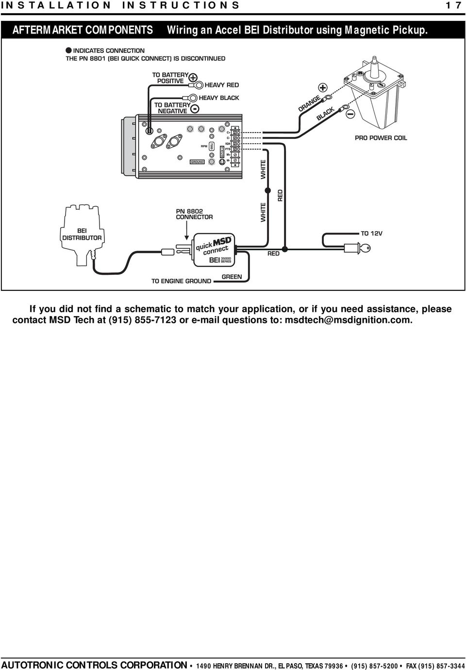
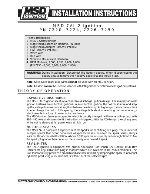
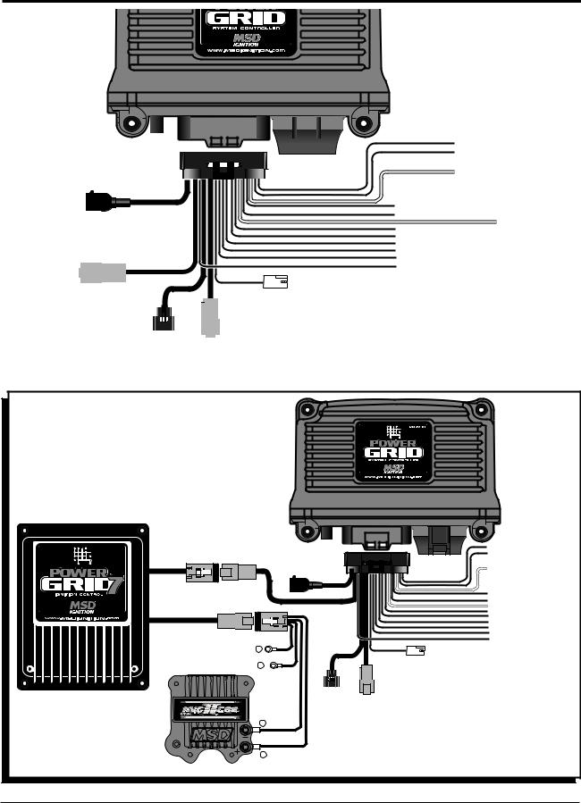
Msd 7al2 wiring diagram. Wiring an Older MSD 8972 Timing Retard Box - YouTube In this video I explain how to wire an MSD 8972 Multi-Step Retard box. PDF MSD 7AL-2 Ignition PN 7220, 7224, 7226, 7250 MSD 7AL-2 Ignition PN 7220, 7224, 7226, 7250 Parts Included: 1 - MSD 7 Series Ignition 1 - Mag Pickup Extension Harness, PN 8860 1 - Mag Pickup Adapter Harness, PN 8859 1 - Coil Harness, PN 8863 1 - White Wire 1 - Red Wire 4 - Vibration Mounts and Hardware 4 - RPM Modules, 3,000, 7,000, 8,000, 9,000 (PN 7250 - 3,000, 5,000, 6,000, 7,000) Power Grid To 7al-2 Wiring Diagram - Holley to battery positive o heavy red o heavy black to batterya negative 0000 c mso rpm receptical white red pro o org bait power coil v. net o elk [email protected] - tarotbylaz.us email protected] From BI7JTA'S Wiki for MMDVM. 4 dBW. Extra cooling is a good thing Unboxing a Motorola SLR 5000 Two-Way Radio Repeater GR1225 Teardown and My 12VDC Mod Portable Radio Repeater Project, Realities Of Building A HomeBI7JTA'S Wiki for MMDVM Apr 16, 2018 · 6, @DW4CHZ maxtrac motorola ,two radio are working good without any adjustment on board 7, …
PDF MSD 8737 RPM Module Selector Installation Instructions Figure 2 Wiring a Two Step to a Latching Relay. INSTALLATION INSTRUCTIONS MSD IGNITION• • (915) 857-5200 • FAX (915) 857-3344 Figure 4 Wiring a Three Step to a Timing Control for Multiple Retards. PART NO. AUTOTRONIC CONTROLS CORPORATION SERIAL NO.. MSD 8737 Three Step Module Selector - Holley As an example, we'll use a drag car with a Three Step Module Selector plugged into the rpm socket of a 7AL-2 Ignition. The different rpm modules are activated when 12 volts are applied to a corresponding wire. By connecting one wire to the line-lock circuit, one module will be activated during the burnout. PDF MSD 7230 Ignition Kit Installation Instructions MSD IGNITION • • (915) 857-5200 • FAX (915) 857-3344 oPtIoNAL WIRING This Wiring Section details the optional features of the MSD 7AL-3 and how to wire each system. StARt RetARD The Start Retard of the 7AL-3 is designed to ease starting on engines with locked timing, high compression and a lot of advance. MSD 7330 MSD 7AL-3 Ignition Control - Holley MSD Magnetic Pickup Cable - Shielded - 6 Foot. $41.54. Part# 8862. For racers that want adjustments at their fingertips, the 7AL-3 is the right choice. The 7AL-3 packs high voltage with four step retards, three rev limits and an rpm switch. All of the features are adjusted using plug-in modules including the 3-Step Rev Control and Multi-Step ...
MSD 7222 MSD 7AL-2 Ignition Control - Holley MSD 7AL-2 Ignition Control A staple in the drag race community, features a built-in 2 step rev control and its famous high output spark energy. Part # 7222 Be the first to write a review Estimated Shipping Date: Coming Soon Notify Me When Available Free Shipping Your Price $722.95 Suggested Retail $804.00 Add To Cart PDF MSD Power Grid System Controller PN 7730/77303 The System Controller can also be used with other MSD Ignitions such as the 7AL-2, MSD 8-Plus, and the Pro-Mag series. In order to use the rev limiting features of the System Controller the paired ignition must have a built-in Soft Touch Rev Control that uses plug-in RPM modules. Pages 10-12 show wiring diagrams Msd 7al3 Wiring - Wiring Diagram Pictures - schematron.org MSD IGNITION • schematron.org • () • FAX () oPtIoNAL WIRING This Wiring Section details the optional features of the MSD 7AL-3 and how to wire each system. StARt RetARD The Start Retard of the 7AL-3 is designed to ease starting on engines with locked timing, high compression and a lot of advance. wiring diagrams and tech notes - MPS Racing. Msd 7al-2 plus problem - Chevy Nova Forum Some of the diagrams show this white wire connected to a orange wire but I am so confused right now I stepped away from the car. Any help would be great and just in case it matters the car is my 70 Nova and the distributor is a MSD pro-billet 85551 and the engine harness is stock .
MSD 7AL-2 PLUS INSTALLATION INSTRUCTIONS MANUAL Pdf ... The 7AL-2 Plus Ignition is equipped with a 2-step rev control. The Ignition will accept two rpm. modules so two different rev limits can be set. One rev limit can be used for overrev protection while. the second limit can be activated on the starting line for a lower rpm limit to assist in staging and. for consistent holeshots.
Msd 7al Wiring Diagram An MSD 7AL-2 Plus Ignition Control will operate on any negative ground, 12 volt .. The following wiring diagrams illustrate numerous installations on different vehicles. Note: Solid Core spark plug wires cannot be used with an MSD Ignition.
Msd 7al-2 Wiring Diagram 7220 Msd Wiring Diagrams Brianesser Rh Beta Ford 6al Diagram Digital 7. Msd 7al 2 Wiring Diagram Schematic. Msd 7al 2 Wiring Diagram Find great deals for MSD Ignition Shop with confidence on eBay! Picture 3 of 6; Picture 4 of 6. 3. MSD Ignition Control 7AL-2 FREE SHIPPING.
PDF PN 7330 - Holley You must identify which module your distributor has to determine which wiring diagram to use. Count the number of pins or terminals on the module and follow the diagram for a 4-pin or 7-pin module. RAS ON/OFF OUTPUT RAS IGN TACH START RETARD PNTS M+ M- RET #1 RET #2 RET #3 RET #4 LAUNCH BURNOUT COIL + COIL - BATT - BATT +
PDF MSD Start/Retard Control PN 8982 Figure 6 Wiring an MSD 7 Series Ignition with Points/Amplifier. INSTALLATION INSTRUCTIONS MSD IGNITION • • (915) 857-5200 • FAX (915) 857-3344 Figure 8 Wiring a Digital 6-Plus or 7-Plus Ignition with a Mag Pickup. Figure 9 Wiring to an MSD 8 with a Mag Pickup. ...
PDF MSD 8950 RPM Switch Installation Instructions Figure 4 Wiring to an MSD Ignition Control. Figure 5 Wiring with an MSD Relay. Note: Capacitive discharge ignitions only. Figure 6 Wiring with an MSD Timing Control Retard. RPM PART NUMBER 3,000 - 5,200 PN 8670 4,600 - 6,800 PN 8671 6,000 - 8,200 PN 8672 7,600 - 9,800 PN 8673
7al2 Wiring Diagram Oct 10, 2018 · As the wiring diagram shows the “Gray” wire connecting to the “Violet” wire on the two pin connector. Earlier version units that don’t have a “Gray” wire on the pin connector can connect to the “Tach” output connector.5/5 (2). Msd 7al-2 plus ignition, Features • Read online or download PDF • MSD 7AL-2 Ignition Control Installation User Manual.
MSD Power Grid 7730 Wiring Diagram needed. - Holley Okay guys needing your help, I'm new to the grid world! I'm in need of a full wiring diagram for MSD 7730 & 7720 to a Dedenbear Super Crossover #SCO-1 and Dedenbear electric shifter. There also will be single stage of nitrous feeding from direct port Fogger system through a WOT switch. I'm needing the nitrous to activate after transbrake is release.
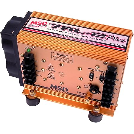
PDF PN 7222/72223 - Holley 1 - MSD 7AL-2 Plus Ignition 1 - White Wire 1 - Mag Pickup Extension Harness, PN 8860 1 - Red Wire 1 - Mag Pickup Adapter Harness, PN 8859 4 - Vibration Mounts and Hardware 1 - Coil Harness, PN 8863 4 - RPM Modules: 3K, 7K, 8K and 9K FEATURES RPM LIMITERS The 7AL-2 Plus Ignition is equipped with a 2-step rev control.
Msd 7al2 Wiring Diagram Nov 16, 2018 · The following diagrams show the installation to a Mallory and an Accel BEI distributor. Figure 3 Primary Wiring to an Accel BEI Distributor. The MSD 7AL-3 will retard the ignition timing approximately 4° compared to other MSD Ignitions. Figure 2 Primary Wiring to an MSD Timing or Boost Control and a Magnetic Pickup.
Power Grid to 7AL-2 - Holley Hi guys, I have bought a power grid controller to replace my faulty 3 step control. But my 7AL2 only has one bank of connectors on the right hand side of the unit not a secondary bank on the left. Does someone have a connection diagram for my style 7AL-2 ? (part no. 7220, as pictured) Attached Images.
Msd Power Grid Wiring Diagram - schematron.org The MSD Power Grid is a versatile timing control that can help solve Wiring diagram shows the connection destination for each wire. Note the.The Power Grid Controller is the brains behind the entire system and can be used with any MSD Ignition or the Pro Mag to provide advance ignition tuning capabilities.
Msd 7al2 To 8972 Wiring Diagram - schematron.org That is why we have assembled this MSD Ignition Wiring Multi Step Retard PN This section covers the MSD 7AL-2 and 7AL-3 Ignition Controls.the coil wiring, it is not necessary to bypass it. This is because the MSD receives its main power directly from the battery. Noise Capacitor: MSD offers a Noise Capacitor or Filter to help eliminate EMI noise.
Msd 7Al2 Wiring Diagram Database - got2bwireless.com Msd 7Al2 Wiring Diagram from annawiringdiagram.com Effectively read a electrical wiring diagram, one has to learn how typically the components within the system operate.
Msd 7al-2 Wiring Diagram 7220 - schematron.org The 7AL-2 has a ground stud just to the left of the terminal strip. Use this to ground other MSD accessories (Figure 2). Ballast Resistor: If your vehicle has a ballast resistor in line with the coil wiring, it is not necessary to bypass it. This is because the MSD receives its main power directly from the battery.








0 Response to "40 msd 7al2 wiring diagram"
Post a Comment