42 in a state machine diagram, a state is represented by a(n) _______.
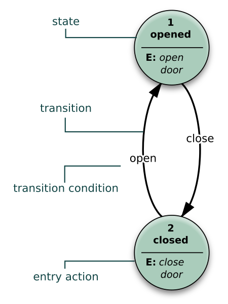
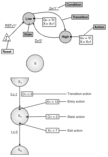
MGS2PM Flashcards - Quizlet In a state machine diagram, a state is represented by a(n) ____. oval. Which of the following is NOT a step in the development of a state machine diagram? a. List all the status conditions for an object. b. Identify state exiting transitions. ... A state machine diagram is used to document the states and transitions of a(n) _____. Lab8_State Machine Diagrams.pdf - CS284 Software Modeling ... States can be represented simply by writing the name of the state inside the rectangular box. However, states can be represented with more details. Entry/exit actions Actions executed on entering and exiting the state, respectively.
ch 5 Flashcards - Quizlet In a state machine diagram, a state is represented by a(n) ____. oval True or False: In an activity diagram, a separate use case may used as part of the workflow.

In a state machine diagram, a state is represented by a(n) _______.
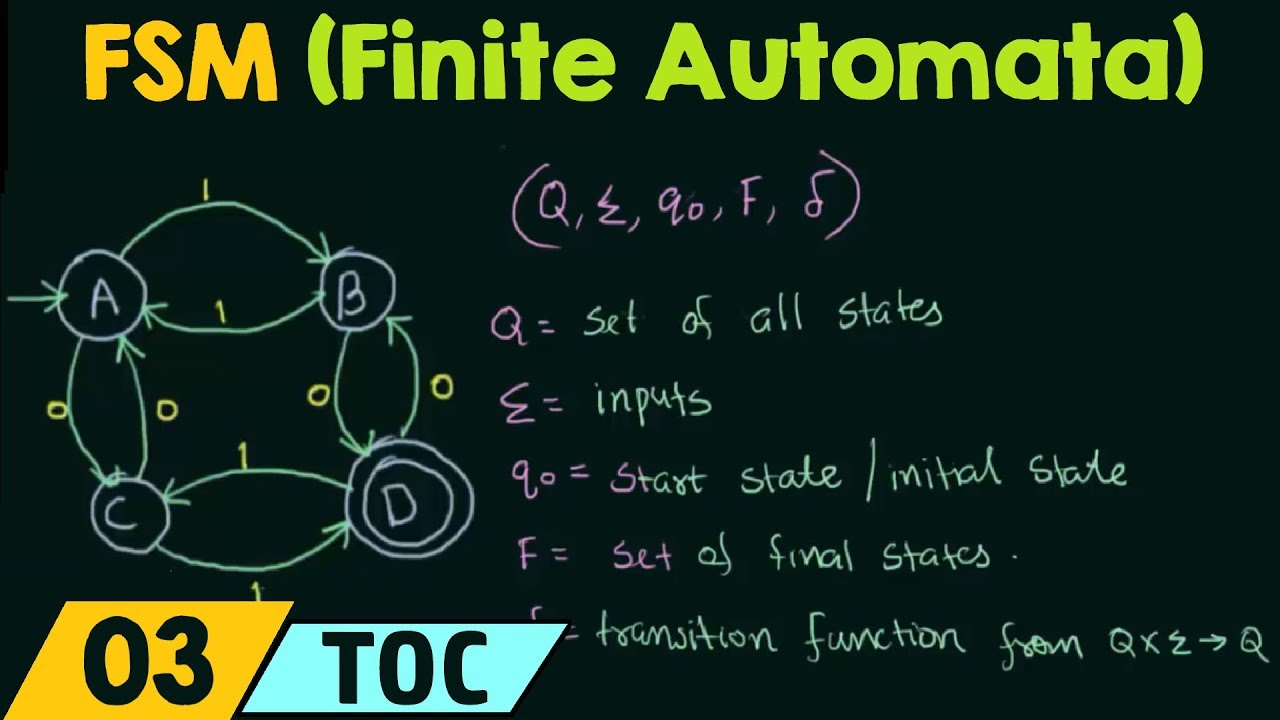
Implementing a Finite State Machine in VHDL - Technical ... Figure 2. Block Diagram Representation of Logic Created for a State Machine. This diagram indicates that there is a set of n flip flops that represent the state. There is also some logic that uses the output of the flip flops and the inputs to the system to determine the next state. State Machine Diagram in UML | What is Statechart Diagram? State machine diagrams are used to represent the behavior of an application. An object goes through various states during its lifespan. The lifespan of an object remains until the program is terminated. The object goes from multiple states depending upon the event that occurs within the object. State Diagram and state table with solved problem on state ... State diagram The state diagram is the pictorial representation of the behavior of sequential circuits. It clearly shows the transition of states from the present state to the next state and output for a corresponding input. In this diagram, each present state is represented inside a circle.
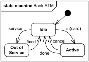
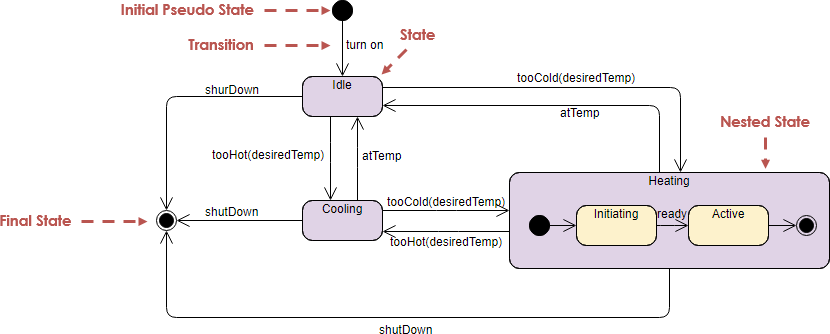
In a state machine diagram, a state is represented by a(n) _______.. What is State Machine Diagram? UML State Machine Diagrams (or sometimes referred to as state diagram, state machine or state chart) show the different states of an entity. State machine diagrams can also show how an entity responds to various events by changing from one state to another. State machine diagram is a UML diagram used to model the dynamic nature of a system. PDF Finite State Machines - Massachusetts Institute of Technology For N states, use ceil(log 2N) bits to encode the state with each state represented by a unique combination of the bits. Tradeoffs: most efficient use of state registers, but requires more complicated combinational logic to detect when in a particular state. Choice #2: "one-hot" encoding For N states, use N bits to encode the state where ... Unified Modeling Language (UML) | State Diagrams ... A state diagram is used to represent the condition of the system or part of the system at finite instances of time. It's a behavioral diagram and it represents the behavior using finite state transitions. State diagrams are also referred to as State machines and State-chart Diagrams.These terms are often used interchangeably. So simply, a state diagram is used to model the dynamic behavior ... State Diagram and state table with solved problem on state ... State diagram The state diagram is the pictorial representation of the behavior of sequential circuits. It clearly shows the transition of states from the present state to the next state and output for a corresponding input. In this diagram, each present state is represented inside a circle.
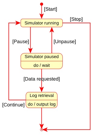
State Machine Diagram in UML | What is Statechart Diagram? State machine diagrams are used to represent the behavior of an application. An object goes through various states during its lifespan. The lifespan of an object remains until the program is terminated. The object goes from multiple states depending upon the event that occurs within the object. Implementing a Finite State Machine in VHDL - Technical ... Figure 2. Block Diagram Representation of Logic Created for a State Machine. This diagram indicates that there is a set of n flip flops that represent the state. There is also some logic that uses the output of the flip flops and the inputs to the system to determine the next state.
Analysis and Design: Unit_5_ Extending_the_Requirements_Models

State Machine Diagram Tutorial | Lucidchart

State Machine Diagram vs Activity Diagram

Independent states in a state machine diagram - Project ...

State Machine Diagram example of a secure hardware controller ...

State Machine Diagram - an overview | ScienceDirect Topics
UML State Machine Diagrams - Overview of Graphical Notation

State Machine Diagram Chapter 5 Introduction Pages ppt download

State Machines

Analysis and Design: Unit_5_ Extending_the_Requirements_Models

State Transition Table - an overview | ScienceDirect Topics
What Is a State Machine Diagram?
UML State Machine Diagram.Design Elements | UML state machine ...

Finite-state machine - Wikipedia
State diagram - Wikiwand
Finite-State-Machine-Diagram | Finite-State-Machine-Diagram ...

What is State Machine Diagram?
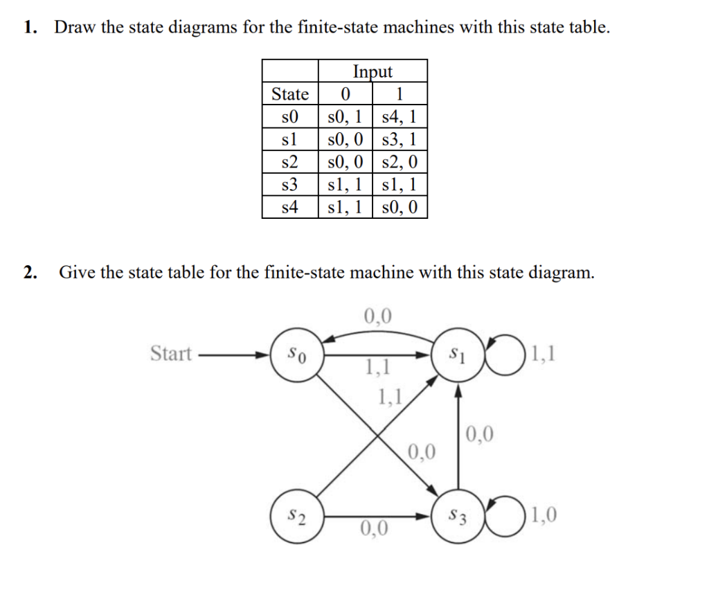
Solved Draw the state diagrams for the finite-state machines ...
How I Learned to Stop Worrying and ❤️ the State Machine

State Machine diagram elements

State Machine Diagram | Innoslate Help Center
State diagram - Wikiwand

State Machine Diagram - UML 2 Tutorial | Sparx Systems
Finite State Machine (Finite Automata)

State Transition Diagram - an overview | ScienceDirect Topics

Adding regions to a UML composite state or state machine ...

State diagram of the finite state machine that controls each ...
State Machine Diagram Tutorial

State Transition Diagram - an overview | ScienceDirect Topics
What is State Machine Diagram?

State Diagram Example — Online Store | UML State Machine ...

State Machine Diagram Chapter 5 Introduction Pages ppt download
State Machine Diagram is a UML diagram suitable for | Chegg.com
State Machine Diagram Tutorial

UML 2 State Machine Diagramming Guidelines

UML 2 State Machine Diagrams: An Agile Introduction

State Machine Diagram - UML 2 Tutorial | Sparx Systems

State Machine Diagram Tutorial | Lucidchart
State Diagram and state table with solved problem on state ...
Solved You are given the following state diagram of a finite ...

A Finite State Machine Model for Requirements Engineering ...

Finite State Machine | Our Pattern Language
0 Response to "42 in a state machine diagram, a state is represented by a(n) _______."
Post a Comment