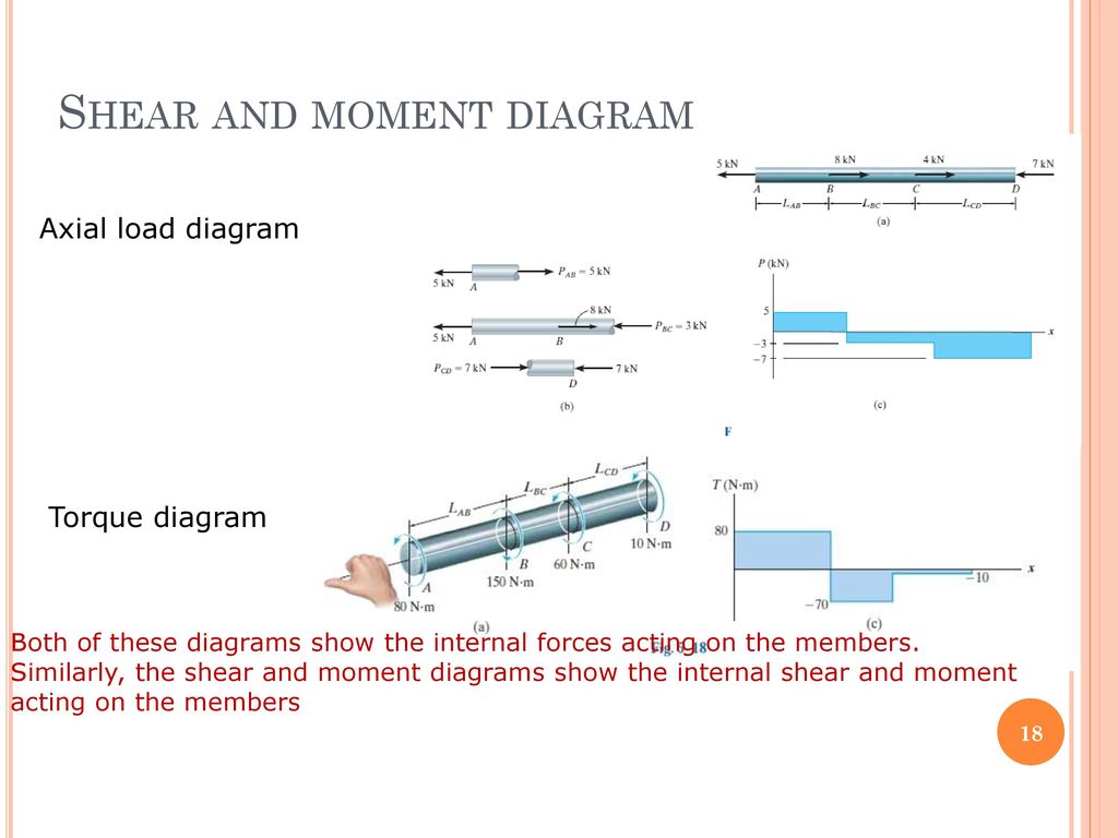
38 moment and shear diagram
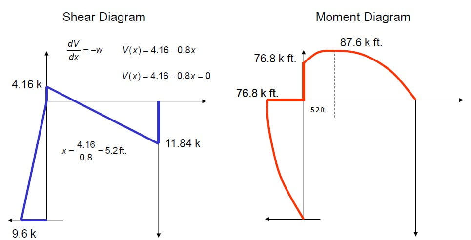
Shear Moment Diagrams: The Best Guide to Using Them ... Before we get down to the nuts and bolts of the diagrams, we need to make every effort to set us up for success. This is done by creating a sign convention. It doesn’t really matter which direction your signs are, what really matters is that you are consistent with it. I choose to use the standard convention, shown below, which has the compressive ... Shear and Moment Diagrams - Memphis Shear and Moment Diagrams Let's draw a free body diagram of the small segment of length xand apply the equations of equilibrium. w= w(x) x x x Shear and Moment Diagrams Since the segment is chosen at a point xwhere there is no concentrated forces or moments, the result of this analysis will notapply to points of concentrated loading w= w(x) x x x
Shear And Bending Moment Diagrams For Frames ... Draw the shear and moment diagrams for the following frame: First, find as many external reactions as possible. Second, cut the frame into its component members and find the internal reactions Next, solve the equations of equilibrium for each member. Let's start with member AB. Next, solve the equations of equilibrium for member CD.

Moment and shear diagram
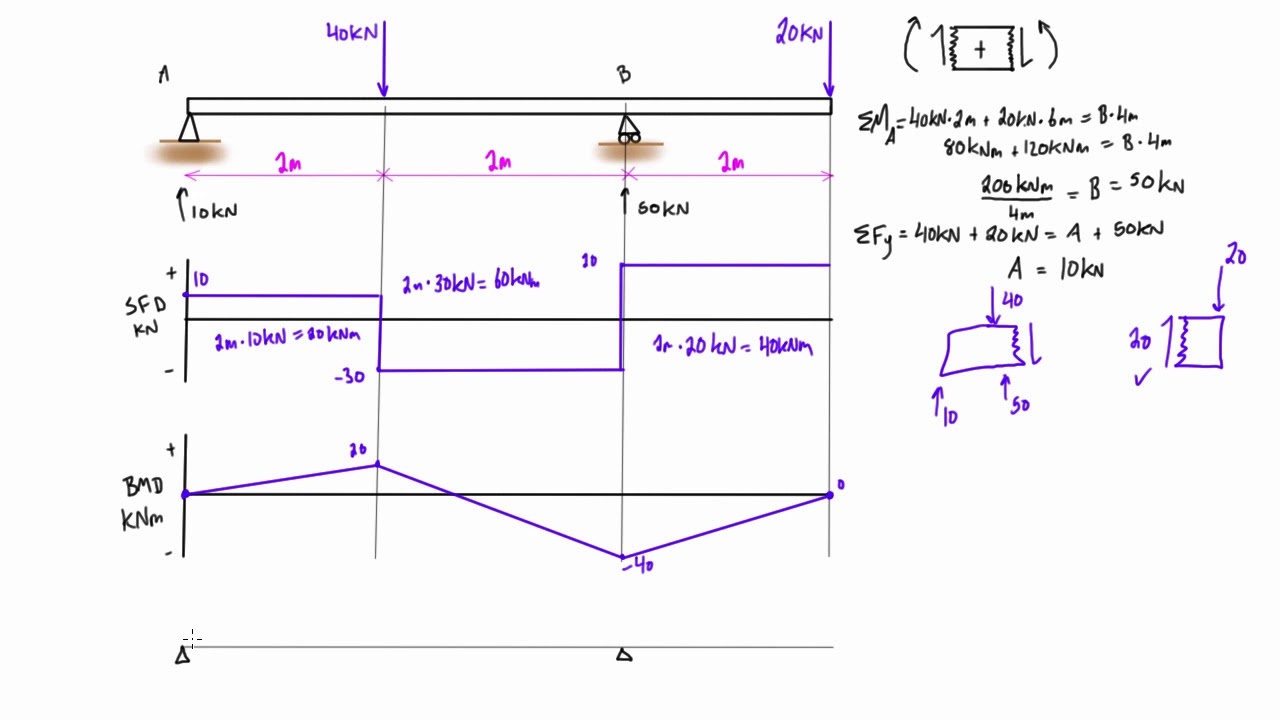
How to Calculate and Draw Shear and Bending Moment Diagrams These instructions will help you to calculate and draw shear and bending moment diagram, as well as draw the resulting deflection. Knowing how to calculate and draw these diagrams are important for any engineer that deals with any type of structure because it is critical to know where large amounts of loads and bending are taking place on a beam so that you can make sure your structure can ... PDF Structural Axial, Shear and Bending Moments Shear and bending moment diagrams depict the variation of these quantities along the length of the member. Proceeding from one end of the member to the other, sections are passed. After each successive change in loading along the length of the member, a FBD (Free Body Diagram) is drawn to determine the equations express-ing the shear and ... Shear force and bending moment diagram and examples ... Calculate the shear force and bending moment for the beam subjected to a concentrated load, then draw the shear force diagram (SFD) and bending moment diagram (BMD). Answer: By taking the moment at A, MA = 0 - RBy × 5 + 15 × 3 = 0 RBy = 9 kN Fy = 0 RAy + RBy = 15 RAy = 15 - 9 RAy = 6 kN Fx = 0 , RAx = 0 Shear force and bending moment diagram
Moment and shear diagram. Engineering at Alberta Courses » Shear and moment ... 4- Write the equations of equilibrium for the resultant segment and solve for the shear force and bending moment at ,. Therefore, 5- Plot the functions and on x–y plots, with the x axis representing the distance from the left end of the beam, and the y axis representing the values of and .The plot gives a shear force diagram (SFD) and the plot gives a bending moment … w=12P=47use moment distribution method and solve for ... w=12. P=47. use moment distribution method and solve for reactions draw the shear and moment diagram. Show transcribed image text. Expert Answer. Who are the experts? Experts are tested by Chegg as specialists in their subject area. We review their content and use your feedback to keep the quality high. Transcribed image text: w (kN/m) Α ΕΙ ... Shear and Moment Diagram Example 2 - Mechanics of ... Example of drawing a shear and moment diagram graphically for a simply supported beam with a concentrated moment and linearly distributed load. I recommend ... Free Online Beam Calculator | SkyCiv Engineering The beam reaction calculator and Bending Moment Calculations will be run once the "Solve" button is hit and will automatically generate the Shear and Bending Moment Diagrams. You can also click the individual elements of this LVL beam calculator to edit the model. Beam Reaction Calculator
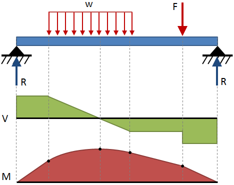
4.1: Shear and Bending Moment Diagrams - Engineering ... Sep 02, 2021 · The shear diagram crosses the V = 0 axis at x = 5 L / 8, and at this point the slope of the moment diagram will have dropped to zero. The maximum value of M is 9 q 0 L 2 / 32, the total area under the V curve up to this point. 6. After x = 5 L / 8, the moment diagram falls parabolically, reaching zero at x = L. Singularity functions Shear and moment diagram - Wikipedia Shear and bending moment diagrams are analytical tools used in conjunction with structural analysis to help perform structural design by determining the value of shear force and bending moment at a given point of a structural element such as a beam.These diagrams can be used to easily determine the type, size, and material of a member in a structure so that a given set of … PDF Chapter 4 Shear and Moment In Beams - ncyu.edu.tw 4.4 Area Method for Drawing Shear- Moment Diagrams Useful relationships between the loading, shear force, and bending moment can be derived from the equilibrium equations. These relationships enable us to plot the shear force diagram directly from the load diagram, and then construct the bending moment diagram from the shear force diagram. PDF Beam Diagrams and Formulas BEAM DIAGRAMS AND FORMULAS Table 3-23 (continued) Shears, Moments and Deflections 7. SIMPLE BEAM-CONCENTRATED LOAD AT CENTER Total Equiv. U naorm Load ... .. ........ .. .. . .. ... . .. .. .. .. = 2 P R=V .................................................................. =~ M,..... (at point of load) ....... ... ...... . :fl.
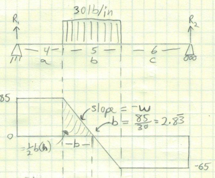
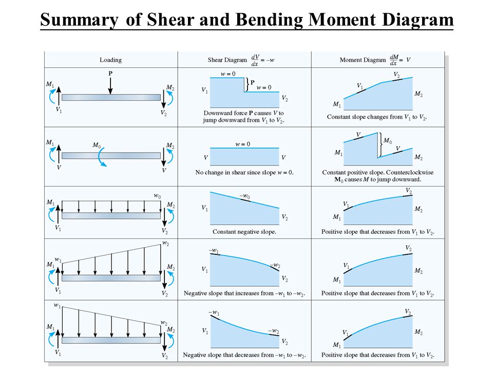
6.2 Shear/Moment Diagrams - Engineering Mechanics: Statics As you move right in your plot, the moment diagram will primarily be the integral of the shear diagram, except… Jump upwards by the magnitude of the moment for any negative (clockwise) moments. Jump downwards by the magnitude of the moment for any positive (counter-clockwise) moments. You can ignore any forces in the free body diagram. PDF 4. Bending Moment and Shear Force Diagram xThe process of obtaining the moment diagram from the shear force diagram by summation is exactly the same as that for drawing shear force diagram from load diagram. xThe bending moment curve is continuous unless there is a point moment on the beam. The curve then "jumps" by the magnitude of the point moment (+ for CW moment). PDF Reactions, Shear Force and Moment Diagrams Dr. M.E. Haque, P.E. Beam Reactions, Shear and Moment (Page 7 of 12) w L Sym. 2 / 8 - w x2 /2 w x2 /2 P 1 L / 4 P 2 x w L / 2 + P 1 / 2 MOMENT DIAGRAMS Fig. 1 Fig. 2 Fig. 3 Algebraic summation of coordinates of these three moment diagrams will produce the final moment diagram. PDF Rules for Shear and Moment Diagrams - Beason Brackin Rules for Shear and Moment Diagrams 1. The slope of the shear diagram at any point is equal to (-) the load intensity at the same point. 𝑑𝑉 𝑑 =− 2. The change in shear between two points on the shear diagram is equal to (-) the area under the loading diagram between the same two points. ∆𝑉 =𝑉 −𝑉 =−∫ 𝑑
Shear and moment diagram - Wikipedia
Ultimate Guide to Shear Force and Bending Moment Diagrams ... Being able to draw shear force diagrams (SFD) and bending moment diagrams (BMD) is a critical skill for any student studying statics, mechanics of materials, or structural engineering. There is a long way and a quick way to do them. The long way is more comprehensive, and generates expressions for internal shear and internal bending moment in ...
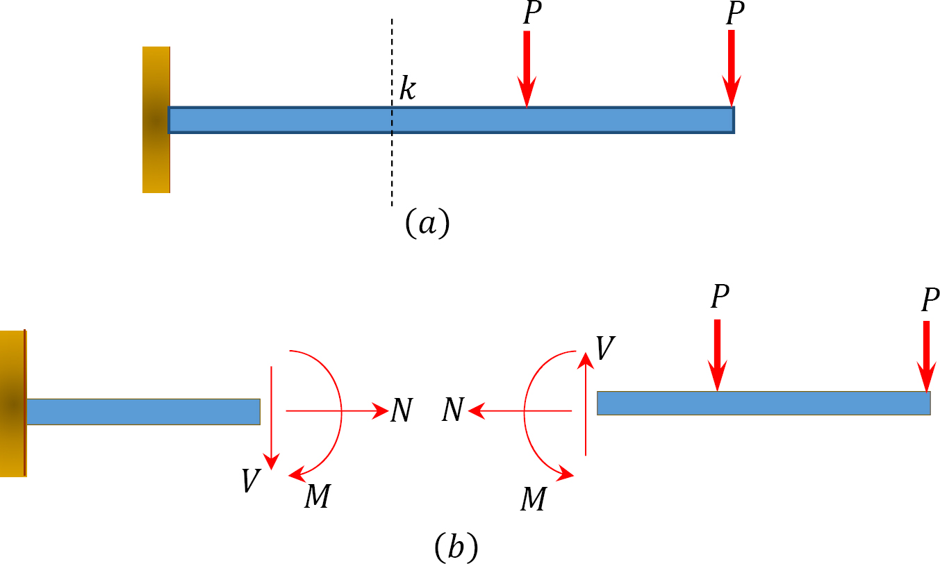
1.4: Internal Forces in Beams and Frames - Engineering LibreTexts
Understanding Shear Force and Bending Moment Diagrams ... This video is an introduction to shear force and bending moment diagrams.What are Shear Forces and Bending Moments?Shear forces and bending moments are resul...

Shear force and bending moment diagram - MechanicalStuff4u
Bending Moment and Shear Force Diagram Calculator | The ... Bendingmomentdiagram.com is a free online calculator that generates Bending Moment Diagrams (BMD) and Shear Force Diagrams (SFD) for most simple beams. The calculator is fully customisable to suit most beams; which is a feature unavailable on most other calculators.

Draw the shear force and bending moment diagrams for the beam ...
Mechanics eBook: Shear/Moment Diagrams Mechanics eBook: Shear/Moment Diagrams Chapter 1. Stress/Strain 2. Torsion 3. Beam Shr/Moment 4. Beam Stresses 5. Beam Deflections 6. Beam-Advanced 7. Stress Analysis 8. Strain Analysis 9. Columns Appendix Basic Math Units Basic Equations Sections Material Properties Structural Shapes Beam Equations Search eBooks Dynamics Statics Mechanics Fluids
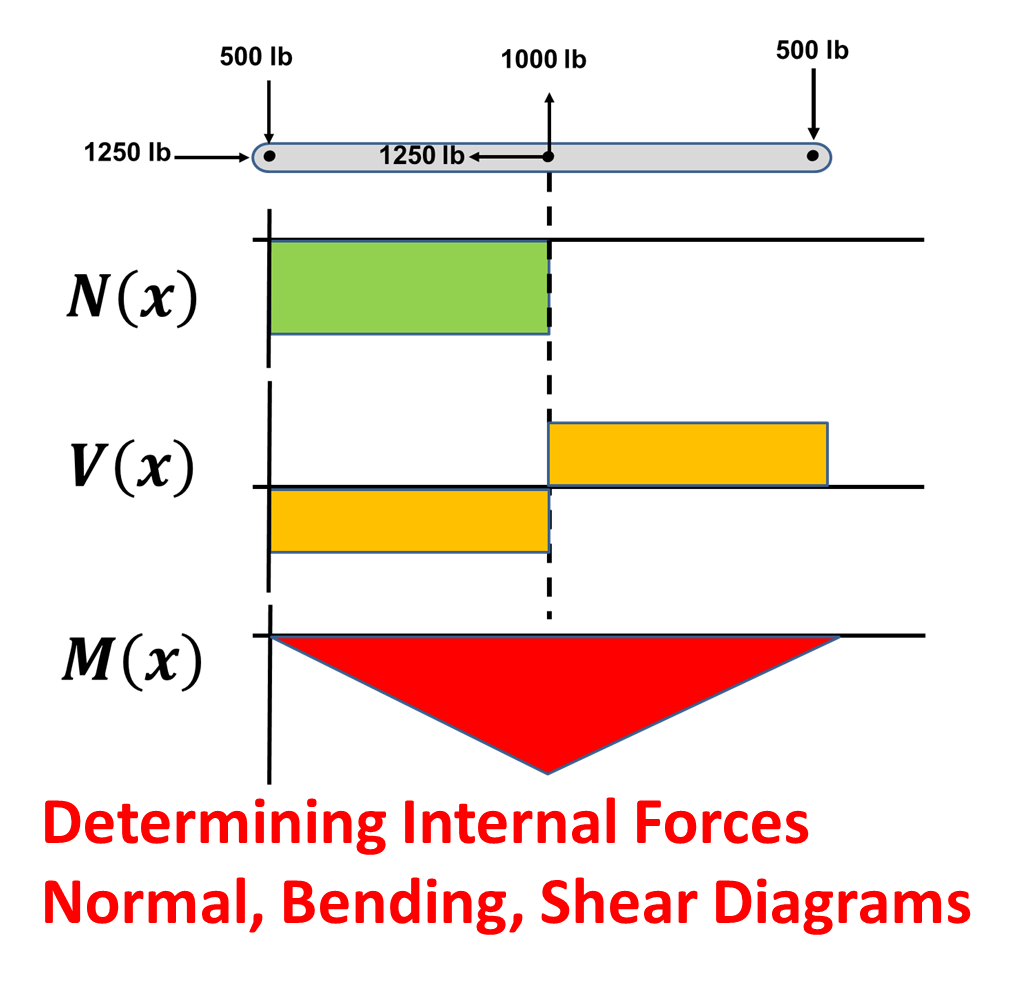
Determining Internal Forces: Normal, Shear, and Bending ...
8.4: Shear and Bending Moment Diagrams - Engineering ... Shear and Bending Moment Diagrams Shear and moment diagrams are graphs which show the internal shear and bending moment plotted along the length of the beam. They allow us to see where the maximum loads occur so that we can optimize the design to prevent failures and reduce the overall weight and cost of the structure.

Shear Force and Bending Moment Diagrams - Wikiversity
Shear and Moment Diagrams | Strength of Materials Review ... Shear and Moment Diagrams Consider a simple beam shown of length L that carries a uniform load of w (N/m) throughout its length and is held in equilibrium by reactions R 1 and R 2. Assume that the beam is cut at point C a distance of x from he left support and the portion of the beam to the right of C be removed.
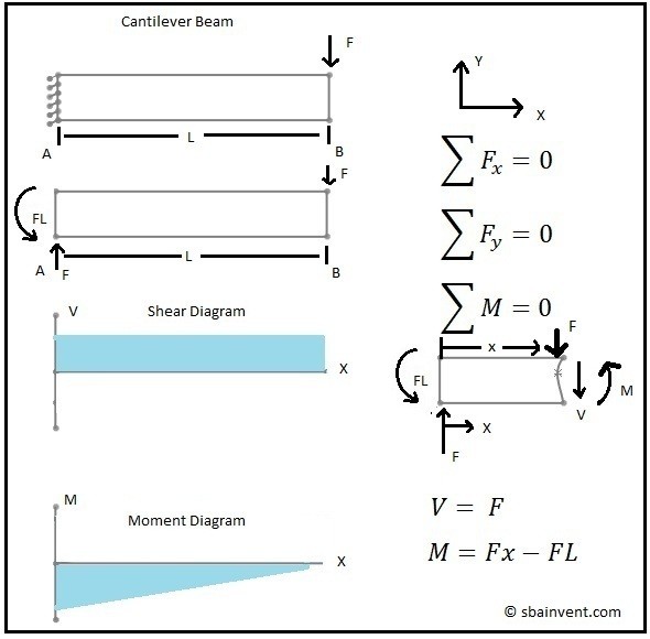
Shear force and Bending Moment diagram for cantilever
The Ultimate Guide to Shear and Moment Diagrams ... Jul 23, 2021 · 4.0 Building Shear and Moment Diagrams In the last section we worked out how to evaluate the internal shear force and bending moment at a discrete location using imaginary cuts. But to draw a shear force and bending moment diagram, we need to know how these values change across the structure.

Brief Information About Shear Force And Bending Moment ...
Mechanics Map - Shear and Moment Diagrams The shear and moment diagrams are both used primarily in the analysis of horizontal beams in structures, such as floor joists, ceiling joists, and other horizontal beams used in construction. The horizontal beams under this bridge surface will be supporting load forces perpendicular to the length of the beam.
Shear Force And Bending diagrams - Roy Mech
PDF Beam Design Formulas With Shear and Moment Shear and moment diagrams and formulas are excerpted from the Western Woods Use Book, 4th edition, and are provided herein as a courtesy of Western Wood Products Association. Introduction Notations Relative to "Shear and Moment Diagrams" E = modulus of elasticity, psi I = moment of inertia, in.4 L = span length of the bending member, ft.
Shear and Moment Diagrams - S.B.A. Invent
Shear and Moment (3) (1).pdf - Chapter 4 Shear and Moment ... It is also noted that the ordinate of moment diagram depends on the area of the shear diagram. Positive areas of the shear diagram are added and negative areas are subtracted in order to obtain the ordinate of the moment diagram. 2. Draw the shear and moment diagram for the beam loaded as shown without writing the shear and moment equations.

Shear force and bending moment diagram practice problem #3
Statics eBook: Shear and Moment Diagrams I Shear and Moment Diagrams If the shear equations (Eqs. 1 and 3) are graphed on one single axis and the moment equations (Eqs. 2 and 4) on another single axis, the shear and moment diagrams are obtained as shown on the left. The location for maximum and minimum shear force and bending moment are easily found and evaluated. Number of Sections

Shear Force Diagram - an overview | ScienceDirect Topics
Statics: Shear and Bending Moment Diagrams Section 8.4 Shear and Bending Moment Diagrams. Beams are structural elements primarily designed to support vertical loads. When designing a beam it is important to locate the points of maximum shear and maximum moment and their magnitudes because that's where the beam is most likely to fail.
Mechanics of Materials Chapter 4 Shear and Moment In Beams
Relationship Between Load, Shear, and Moment | Strength of ... When the shear diagram is decreasing, the moment diagram is concave downward. Sign Convention The customary sign conventions for shearing force and bending moment are represented by the figures below. A force that tends to bend the beam downward is said to produce a positive bending moment. A force that tends to shear the left portion of the beam …
Shear and moment diagram - Wikipedia
Shear force and bending moment diagram and examples ... Calculate the shear force and bending moment for the beam subjected to a concentrated load, then draw the shear force diagram (SFD) and bending moment diagram (BMD). Answer: By taking the moment at A, MA = 0 - RBy × 5 + 15 × 3 = 0 RBy = 9 kN Fy = 0 RAy + RBy = 15 RAy = 15 - 9 RAy = 6 kN Fx = 0 , RAx = 0 Shear force and bending moment diagram
Shear Force And Bending diagrams - Roy Mech
PDF Structural Axial, Shear and Bending Moments Shear and bending moment diagrams depict the variation of these quantities along the length of the member. Proceeding from one end of the member to the other, sections are passed. After each successive change in loading along the length of the member, a FBD (Free Body Diagram) is drawn to determine the equations express-ing the shear and ...

structural engineering - How to plot bending moment diagram ...
How to Calculate and Draw Shear and Bending Moment Diagrams These instructions will help you to calculate and draw shear and bending moment diagram, as well as draw the resulting deflection. Knowing how to calculate and draw these diagrams are important for any engineer that deals with any type of structure because it is critical to know where large amounts of loads and bending are taking place on a beam so that you can make sure your structure can ...
structural engineering - Bending moment diagram from shear ...
Shear force and bending moment diagram practice problem #8
![Cantilever Beam: Shear Force and Bending Moment Diagram [SFD BMD Problem 2] By Shubham Kola | Facebook](https://lookaside.fbsbx.com/lookaside/crawler/media/?media_id=257535155732524&get_thumbnail=1)
Cantilever Beam: Shear Force and Bending Moment Diagram [SFD BMD Problem 2] By Shubham Kola | Facebook
The Ultimate Guide to Shear and Moment Diagrams ...

Solved Draw the shear force and bending moment diagrams in ...
Shear And Bending Moment Diagrams For Frames - Construction How
Mechanics Map - Shear and Moment Diagrams
Shear Moment Diagrams: The Best Guide to Using Them ...
Shear Load and Bending Moment Diagrams

How to Calculate and Draw Bending Moment and Create BMD ...

Mechanics Map - Shear and Moment Diagrams

Shear Force and Bending Moment Diagrams - Wikiversity

Shear Force and Bending Moment Diagrams - Wikiversity
shear force and bending moment diagram - ppt download
Shear Load and Bending Moment Diagrams
Shear Force and Bending Moment diagram in the horizontal ...
How To Draw Shear Force And Bending Moment Diagram In Case Of ...
Composite Beam Transformed homogeneous beam obtained through ...
Determining the Shear Force and Bending Moment Equations of ...

Drawing Shear Force, Bending Moment Diagram » File Exchange ...
6.2 Shear/Moment Diagrams – Engineering Mechanics: Statics
Beam Stress & Deflection | MechaniCalc
0 Response to "38 moment and shear diagram"
Post a Comment