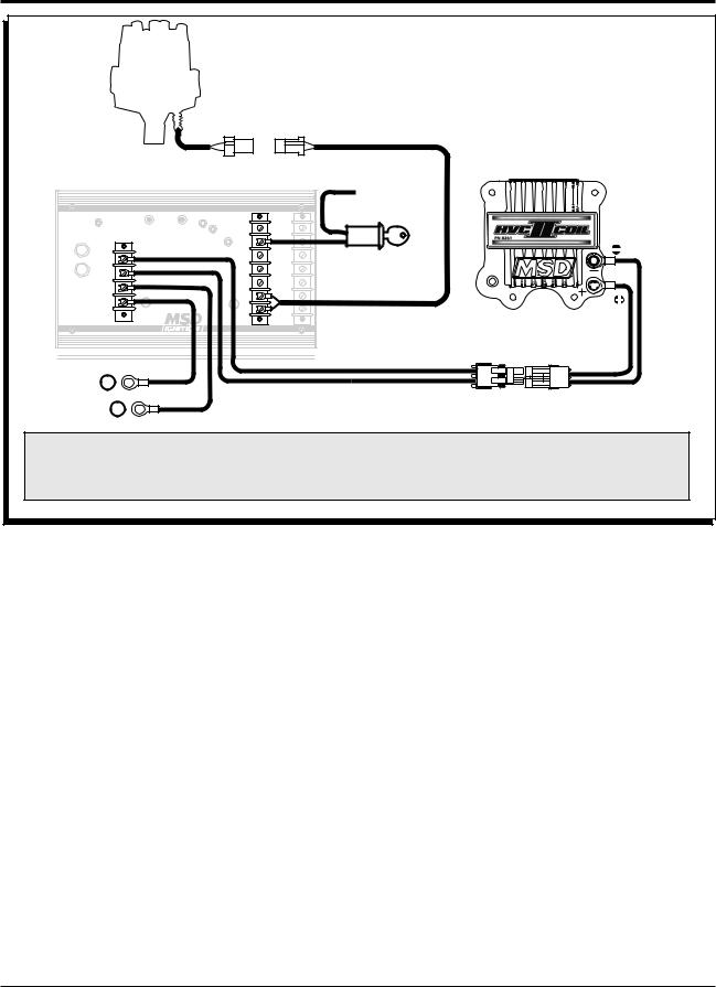
38 msd 7531 wiring diagram
This can be done using a 4 pole, Double-Throw switch for a dual mag installation or a 2 Pole, Double-Throw switch for a single mag installation (See wiring diagrams*). A word of caution here, extending magnetic pickup leads can introduce EMI (Electro magnetic Interference) or RF (Radio Interference) into the system, this can cause random ... Wiring Diagram For Electric Shift To Msd 7531 Site. Page 1. FBIONĀDES. RACING PRODUCTS, INC. Biondo Racing Products Electric Solenoid Shifter (#ESS). Installation Instructions. Our electric solenoid WIRING DIAGRAMS. 1) When using an MSD RPM Activator Switch follow this diagram. Page 1 The SS5 solenoid shifter is designed to shift 2-speed ...
Msd 7al 2 Wiring Diagram Site Resource. Msd 7al 3 ignition wiring diagram full 2 7230 pn 7220 7224 7226 transbrake kit installation instructions two step control power grid rpm module wire stage ford 460 7330 diagrams and tech notes manualzz site 7720 7730 6a nitrous with promag plus 7222 mallory 29440 coil f3b kawasaki mc1 multiple system 6al users only 6420 12 gm hei distributor harness the ...

Msd 7531 wiring diagram
Msd Pro Mag Information 44 Amp Generator. Diagram msd promag wiring full pro mag timing control diagrams and tech notes manualzz tach converter in pdf format 12 mb com addendum to 7531 reva holley motor ignition information alkydigger pn 8132 8106 electronic points box 8636 chrysler big block crank trigger 44 kill switch relay help with how properly a amp getting know s power grid features ... INSTALLATION INSTRUCTIONS MSD IGNITION • www.msdignition.com • (915) 857-5200 • FAX (915) 857-3344 WIRING GENERAL WIRING INFORMATION Wire Length: All of the wires of the MSD Ignition may be shortened as long as quality connectors are used or soldered in place. To lengthen the wires, use one size bigger gauge wire (10 gauge for wiring chart function pin wire color wire description notes output voltage can be calibrated via msd view . the default output voltage, 0-5v, corresponds to an afr (air fuel ratio) 8-18 of gasoline .a zero (0) volt reading is an afr of 8 and 5v is anafrof18. (2afrpervolts) output to a gauge or daqisanoption. power source
Msd 7531 wiring diagram. Msd Ignition Wiring Diagram 7al Msd Ignition Wiring Diagrams 7531 Wiring Diagram View is one of the pictures that are related to the picture before in the collection gallery, uploaded by autocardesign.org.You can also look for some pictures that related to Wiring Diagram by scroll down to collection on below this picture. If you want to find the other picture or article about Msd Ignition ... MSD IGNITION • www.msdignition.com • (915) 857-5200 • FAX (915) 857-3344. Accessories Dark Blue. This wire activates the Launch Rev Limit and is the main reset wire for several features of the Ignition. When 12 volts are applied to this wire it will activate the Launch Rev Limit. It also 7531 and msd 8 wiring diagrams. Jump to Latest Follow 1 - 19 of 19 Posts. jlawson · Registered. Joined Feb 23, 2007 · 98 Posts . Discussion Starter · #1 · Oct 31, 2009. does anybody have a wiring diagram to wire msd 7531 box to msd 8 with big stuff 3 any help will be appreciated thanx ... MPS Racing
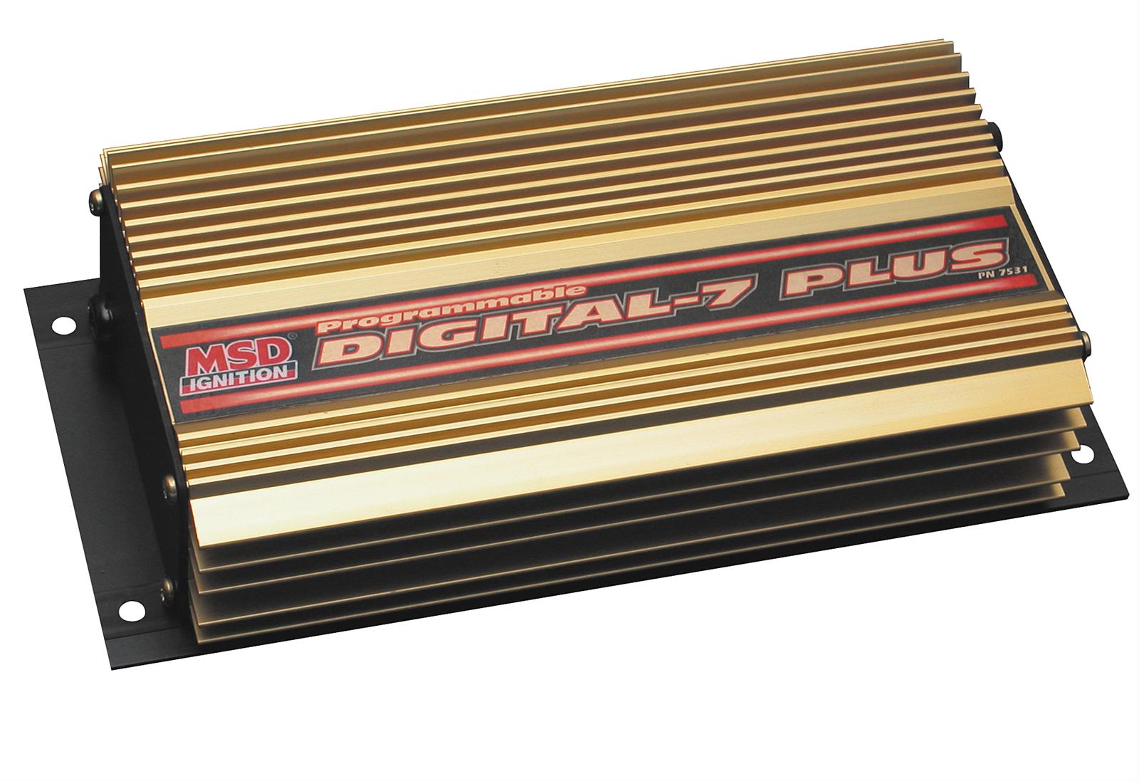
Msd 7531 Wiring. Programmable digital-7 plus • Read online or download PDF • MSD Note : Solid core spark plug wires cannot be used with an MSD Ignition Control. Junior Member. Spooled up. OneFastFox's Avatar. Join Date: May Location : NC! Posts: Default MSD wiring/ transbrake wiring. The Ignition is supplied with wiring harnesses, mounting ... MSD Weathertight Connector - 3-Pin - Qty 1. Self-Lubricating Silicone Seals for Protection Against Water, Dust, Oil, and Other Engine Compartment Fluids. Part# 8172. $12.72. Qty: Add To Cart. Replacement Harness for Programmable Digital-7 Plus. Replacement harness for PN 7531. Part# 8855. MSD IGNITION • www.msdignition.com • (915) 857-5200 • FAX (915) 857-3344 Programmable Digital-7 Plus PN 7531 Parts Included: 1 - Ignition Control, PN 7531 1 - TI Pressure Gauge Harness 1 - MSD Pro-Data+ CD Rom 7531 - MSD Digital-7 & 7AL Series Ignition Boxes is rated 5.0 out of 5 by 1. Rated 5 out of 5 by Danley Cantrell from Has everything you need! Works great definitely worth the money easy install plug and play
MSD Programmable Digital 7 - 7530 or 7531? #1 Post by BBC71Nova » Thu Jan 12, 2006 2:52 am With the 7530 (non "Plus") model of the Programmable Digitial 7 can you still ramp in the timing for a gear? Msd Pro Mag 44 Wiring Diagram. Pro mag 44 kill switch relay wiring msd amp generator electronic points box jumper wire on the tach converter pn 8132 diagrams and tech notes information 7531 reva holley motor. Clarification About Whether You Need The Jumper Wire On 44 Amp Msd Mag When Using Grid Alkydigger Technical Info. MSD • WWW.MSDPERFORMANCE.COM • (915) 857-5200 • FAX (915) 857-3344 Parts Included: 1 - Ignition Control, PN 7531 1 - MSD Pro-Data+ CD Rom 4 - Vibration Mounts & Screws 1 - Shielded Cam Sync Harness 1 - 9-Pin Computer Harness Wiring Diagram For Electric Shift To Msd 7531 Site. That is why we have assembled the MSD Ignition Wiring Diagrams and Tech Notes Book. This book This warranty is void for any products purchased through auction websites. If found to be.. sories such as fuel pumps and electric fans are used, the tachometers, an MSD Shift Light, or rpm activated. ...

Hyundai Accent Can Bus No Need Key Install Original Korean Magicar 7 1 Mile Remote Starter Engine Start Car Alarm Timer Start Starter Box Starter Capstarter Battery Aliexpress
Wiring diagram for electric shift to msd 7531 site. Gaggia accademia parts diagram. 7 pin pollak wiring diagram. Kenwood ddx271 wiring diagram. Vixen ooga horn wiring diagram. Wiring diagram for clarion vz400. Wiring diagram for john deere l120 lawn tractor. Ford solenoid 2701966 wiring diagram.
Msd 7531 Wiring Diagram. 15.04.2019 15.04.2019 0 Comments on Msd 7531 Wiring Diagram. Find MSD Programmable Digital-7 Plus CD Ignitions and get Free Shipping on with the Pro-Data Plus software, PC harness, vibrations mounts, and wiring. Is the coil diagram for the 6 series wiring, the same for a ? ...
msd 7 wiring diagram wiring diagram sheet. Architectural wiring diagrams feat the approximate locations and interconnections of receptacles, lighting, and enduring electrical services in a building. Interconnecting wire routes may be shown approximately, where particular receptacles or fixtures must be upon a common circuit.
Pro mag 44 kill switch relay wiring diagram msd com amp generator electronic points box tech site tach converter pn 8132 mounting clarification about whether you need the jumper wire on when using grid alkydigger technical info 8973 to 7531 reva holley motor life diagrams and notes information manualzz help with how properly a magneto installation instructions 11… Read More »
Wiring Diagrams FT450 Honda K20-24Version: 1.0 | Size: 0.92 MB FT550 8 Cyl Smart CoilVersion: 1.0 | Size: 0.52 MB FT550 6 Cyl Smart CoilVersion: 1.0 | Size: 0.51 MB ...

Msd 6 Hvc Professional Racing Ignition With Msd 6 Hvc Professional Racing Ignition Pn 6601 Is Pdf Document
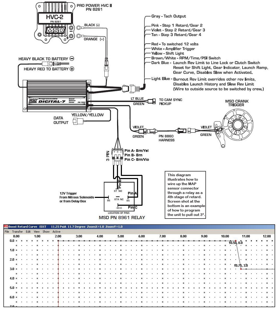
1) Connect step 1 retard pink wire (MSD 7531 box) to the output terminal of the relay that activates the nitrous or directly to the nitrous solenoid itself. 2) After opening the msd pro-data software on the laptop, I will open the data editor menu tree, scroll down to retards, click on step 1 retard, then program my 8* of timing there, ramping ...
Re: msd 7531 with nitrous. #12. Post. by John_Heard » Thu Nov 05, 2015 3:02 pm. No, Dark Blue is the main reset, it's typically hooked up to a transbrake which will signal the start of the run. In your case I'd probably rig me up a switch and connect it to your brake light switch since your foot braking it.
MSD 7531 and a Shifnoid electric shifter solenoid. Using a relay. Cant seem to get it working. I would like to use the yellow wire and not the brn/wht. Please help. Spring Loaded Shifnoid for PG forward pattern if that makes any difference. To wire the relay to your shifnoid will require a 5 pin relay.
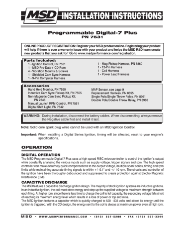
MSD IGNITION • WWW.MSDIGNITION.COM • (915) 857-5200 • FAX (915) 857-3344. Parts I. ncluded: 1 - Ignition Control, PN 7531. 1 - MSD Pro-Data+ CD Rom 4 - Vibration Mounts & Screws 1 - Shielded Cam Sync Harness 1 - 9-Pin Computer Harness Accessories Hand Held Monitor, PN 7550 Inductive Cam Sync Pickup Kit, PN 7555 Non-Magnetic Cam Sync ...
In an inductive ignition the coil must store energy and step up the supplied voltage to maximum strength between. The msd ignition features...
wiring chart function pin wire color wire description notes output voltage can be calibrated via msd view . the default output voltage, 0-5v, corresponds to an afr (air fuel ratio) 8-18 of gasoline .a zero (0) volt reading is an afr of 8 and 5v is anafrof18. (2afrpervolts) output to a gauge or daqisanoption. power source
INSTALLATION INSTRUCTIONS MSD IGNITION • www.msdignition.com • (915) 857-5200 • FAX (915) 857-3344 WIRING GENERAL WIRING INFORMATION Wire Length: All of the wires of the MSD Ignition may be shortened as long as quality connectors are used or soldered in place. To lengthen the wires, use one size bigger gauge wire (10 gauge for
Msd Pro Mag Information 44 Amp Generator. Diagram msd promag wiring full pro mag timing control diagrams and tech notes manualzz tach converter in pdf format 12 mb com addendum to 7531 reva holley motor ignition information alkydigger pn 8132 8106 electronic points box 8636 chrysler big block crank trigger 44 kill switch relay help with how properly a amp getting know s power grid features ...









0 Response to "38 msd 7531 wiring diagram"
Post a Comment