39 cu ni phase diagram
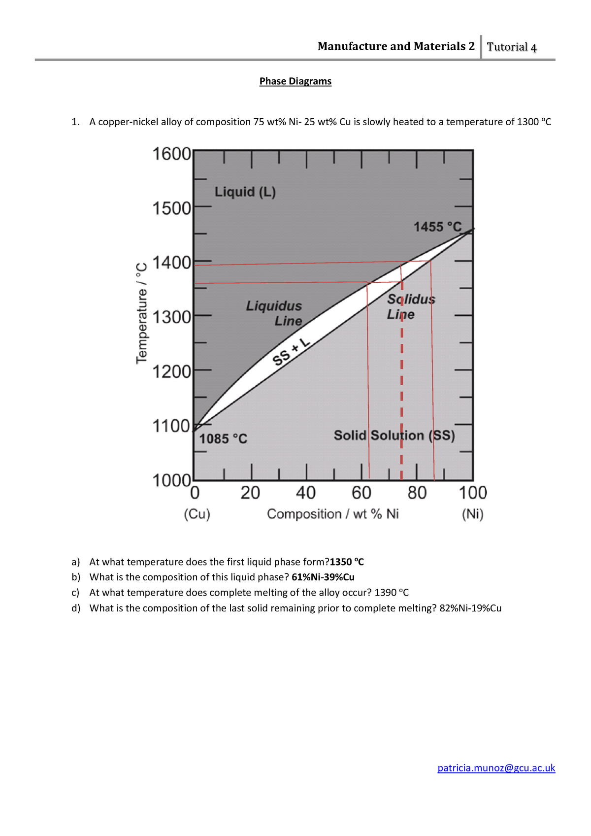
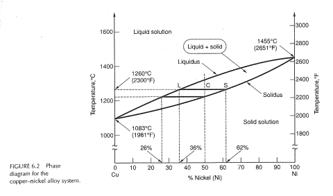
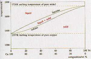
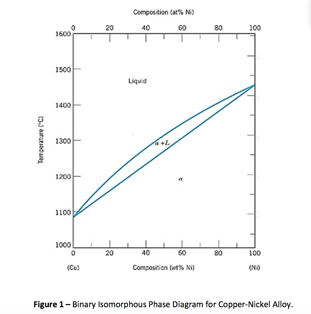
#modimechanicalengineeringtutorials, #mechanicalmagicmechanicallearningtutorials,Welcome to My YouTube Channel MODI MECHANICAL ENGINEERING TUTORIALS.This ch... A phase diagram shows the range of existence of phases in materials with more than one component. The binary phase diagram shown for the copper-nickel alloy indicates that these materials can form both liquid and solid solutions over the full range of composition from Cu to Ni. Above 1728 K, the melting point of pure Ni the alloys ar in the ...
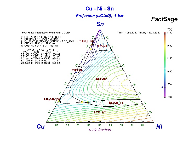
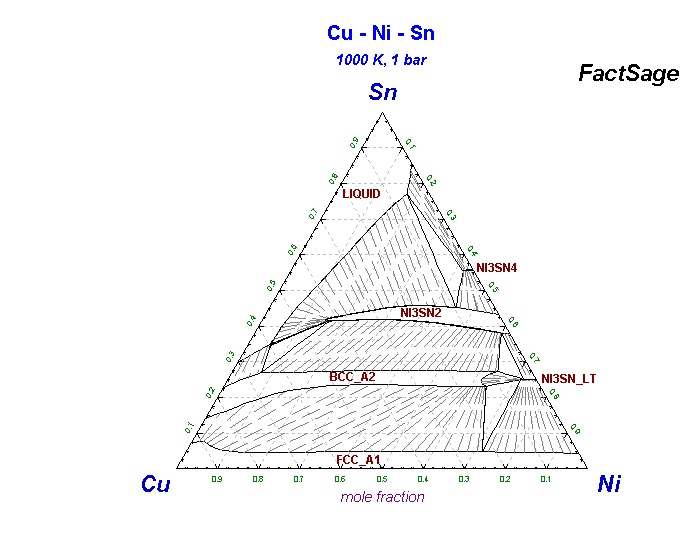
To generate a new Sn-Cu-Ni phase diagram based on reliable experimental data including four liquidus lines at 240 °C, 250 °C, 260 °C, and 270 °C. Characterize the invariant (or invariants) line for the equilibrium between a liquid phase with two IMCs.
Cu ni phase diagram
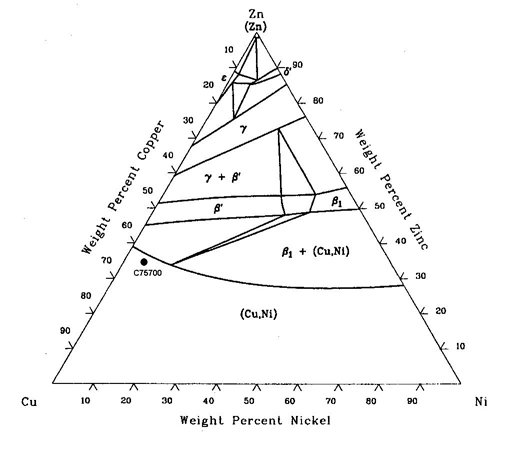
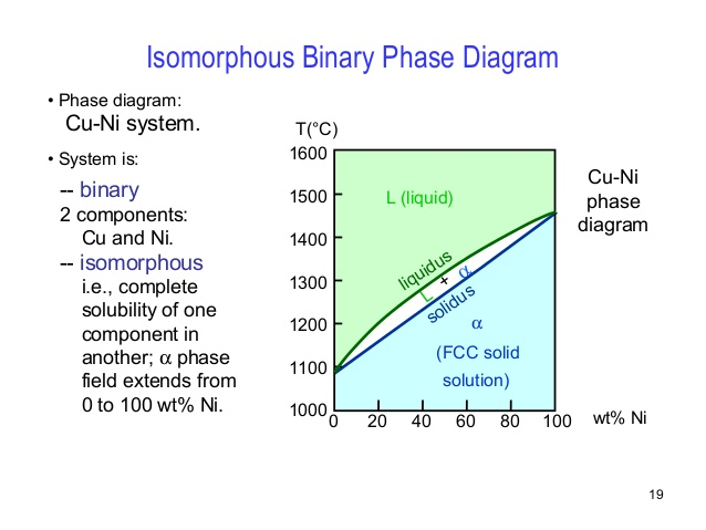
Phase Diagrams • Indicate phases as function of T, Co, and P. • For this course:-binary systems: just 2 components.-independent variables: T and Co (P = 1 atm is almost always used). • Phase Diagram for Cu-Ni system Adapted from Fig. 9.3(a), Callister 7e. (Fig. 9.3(a) is adapted from Phase Diagrams of Binary Nickel Alloys , P. Nash pressure to be constant at one atmosphere. Phase diagrams for materials with more than two components are complex and difficult to represent. An example of a phase diagram for a ternary alloy is shown for a fixed T and P below. Phase diagrams for binary systems ternary phase diagram of Ni-Cr-Fe Binary Phase Diagrams • Indicate phases as function of T, C o, and P (pressure). • For this course: - binary systems: just 2 components. - independent variables: T and C o (P = 1 atmosphere is almost always used). • Phase Diagram for Cu-Ni system • 2 phases: L (liquid) a(FCC solid solution) • 3 phase fields: L L + a a 0 20 40 60 80 ...
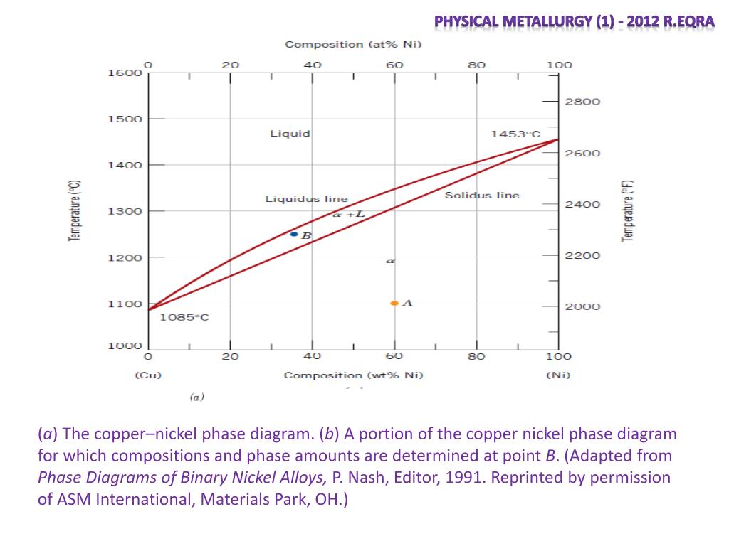
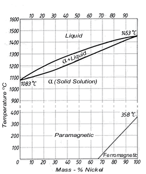
Cu ni phase diagram. Eutectic 1. We have examined isomorphous phase diagrams, and used the example of the Cu-Ni phase diagram. In this module we will examine eutectic phase diagrams. A eutectic system has two components, and they have limited solubility. Upon cooling, the liquid will transform into two mixed solid phases. We will use the Pb-Sn phase diagram as an ... Cu-Ni phase diagram A(1100, 60): 1 phase: B(1250, 35): 2 phases: L + Determination of phase(s) present Melting points: Cu = 1085°C, Ni = 1453 °C Solidus - Temperature where alloy is completely solid. Above this line, liquefaction begins. Liquidus - Temperature where alloy is completely liquid. Below this line, solidification begins. The Cu-Ni and binary phase diagram (Figure 10.3) is the simplest type of binary phase diagrams for two metals. Figure 10.3 shows that Cu and Ni are mutually soluble at room temperature throughout the entire range of compositions. Remember from Chapter 5that we discussed the HumeRothery - In this work, phase relations and thermal stabilities of equilibrium phases in the Cu-Ni-S system have been reviewed. The calculated phase diagram of Cu-N system has been validated. At T > 630 K, in the N-rich corner, large scatter in data has been observed and discussed in detail.
suitable to describe phase relations below ~ 40 at.% Sn at these temperatures. • Because of complex phase transformations, possible metastable phase transformations, coring effects, etc., the experimental investigation of the (Cu,Ni)-rich part is very difficult. • Some of the published sections are erroneous simply from a The binary phase diagram is used for system of two components and its classifications depend on number of phases as; isomorphous contain system with two phases such as Cu-Ni system. 7.3. Al-Cu-Ni PHASE DIAGRAM This phase diagram is helpful in the analysis of 2618-type heat-resistant alloys and 339.0-type piston alloys that contain nickel, copper, and other alloying components (Tables 7.1 and 7.2). The ternary Al7Cu4Ni phase forms in the aluminum corner of the Al-Cu-Ni system. by J Sopousek · 2014 · Cited by 80 — The Cu–Ni nanoalloy phase diagram respecting the nanoparticle size as an extra variable was calculated by the CALPHAD method. The samples of the ...7 pages
The Al 7 Cu 4 Ni 1 phase (i.e. τ), with a small homogeneity range, is the only ternary phase in the Al-Cu-Ni system [10,35,36]. The Al 7 Cu 4 Ni 1 phase has a CsCl-type base structure, where along the c axis 8 Al atoms alternates with 6 heavy atoms (i.e. Cu and Ni) and 2 vacant sites . 0. Phase Diagram 1. Overview 2. Heating & Pouring 3. Solidification and Cooling 2 0. Alloys and Phase Diagram • Pure Metals • Alloys - Solid solutions • Substitutional Solid Solution (Zn/Cn and Cu/Ni) - Atomic radii is similar - Lattice type is the same • Interstitial Solid Solution - Smaller atoms are interstitially located ... Move the mouse over the phase diagram to view temperature and composition at any point. View micrographs for the Cu-Ni system. List all systems with phase diagrams View Notes - Phase_Diagrams_II from APSC 278 at University of British Columbia. Phase Diagrams II Cu-Ni Phase Diagram 1 Binary Eutectic Systems Examples Cu Ag Pb Sn Important Features 3 Single

Solution Tutorial 4 Phase Diagrams Manufacture And Materials 2 Tutorial 4 Phase Diagrams 1 A Studocu
@article{osti_22933591, title = {Experimental Determination of the Sn-Cu-Ni Phase Diagram for Pb-Free Solder Applications}, author = {Henao, Hector M., E-mail: hector.henao@usm.cl and Chu, Ching-shun and Solis, Juan P. and Nogita, Kazuhiro}, abstractNote = {The rapid increase of scrapped electrical products disposed in landfill sites is significantly influencing the environment because of the ...
Meaning of Phase Diagram: A phase diagram is also called an equilibrium or constitutional diagram. It shows the relationship between temperature, the compositions and the quantities of phases present in an alloy system under equilibrium conditions. When temperature is altered many microstructure develop due to phase transformation.
1.2 The Cu-Ni equilibrium diagram. ... The curve which forms the upper boundary of the area of a crystals is termed the 'solidus'. A two-phase area in which liquid and a crystals co-exist is formed between liquidus and solidus. Below a dotted straight line at the bottom right, behaviour is ferromagnetic, above it is paramagnetic. ...
Phase Diagrams • Indicate phases as a function of T, C, and P. • For this course:-binary systems: just 2 components.-independent variables: T and C (P = 1 atm is almost always used). Phase Diagram for Cu-Ni system Fig. 11.3(a), Callister & Rethwisch 9e. (Adapted from Phase Diagrams of Binary Nickel Alloys, P. Nash, Editor, 1991. Reprinted
Answer: Yes, the Cu-Ni phase diagram exhibits a miscibility gap below roughly 600 K. This has been calculated theoretically and measured experimentally: Image source. Thermodynamically, a miscibility gap is almost inevitable in metal systems, which have positive enthalpies of mixing. The free e...
The Cu-Ni nanoalloy phase diagram respecting the nanoparticle size as an extra variable was calculated by the CALPHAD method. The samples of the Cu-Ni nanoalloys were prepared by the solvothermal synthesis from metal precursors. The samples were characterized by means of dynamic light scattering (DLS), infrared spectroscopy (IR ...
This video explains binary phase diagrams, specifically the Cu-Ni System. For further studies: visit https://www.doitpoms.ac.uk/tlplib/phase-diagrams/printal...
A good interpretation of a binary phase diagram that is easy to understand and interpret is the Cu-Ni system. This diagram has three different phase regions ...
Example: Cu-Ni phase diagram (only for slow cooling conditions) Liquidus line: the line connecting Ts at which liquid starts to solidify under equilibrium conditions Solidus: the temperature at which the last of the liquid phase solidifies Between liquidus and solidus: P =2. Chapter 8 9
Part of the phase diagram of the Cu-Ni-Mn system from 0 to 20% Ni and from 30 to 50% Mn is refined with the help of a theoretical analysis and based on the experimental data.
Shown below is the Cu-Ni phase diagram (Figure 9.3a) and a vertical line constructed at a composition of 70 wt% Ni-30 wt% Cu. (a) Upon heating from 1300°C, the first liquid phase forms at the temperature at which this vertical line intersects the α-(α + L) phase boundary--i.e., about 1345°C. )-)-
Phase Diagrams • Indicate phases as function of T, Co, and P. • For this course: -binary systems: just 2 components. -independent variables: T and Co (P = 1 atm is almost always used). • Phase Diagram for Cu-Ni system Adapted from Fig. 9.3(a), Callister 7e. (Fig. 9.3(a) is adapted from Phase Diagrams of Binary Nickel Alloys, P. Nash
The Cu-Ni phase diagram (Figure 9.3a) is shown below; the point labeled "G" represents the 63.8 wt% Ni-36.2 wt% Cu composition at 1250°C. As may be noted, point G lies within the α phase field. Therefore, only the α phase is present; its composition is 63.8 wt% Ni-36.2 wt% Cu.
Binary Phase Diagrams • Indicate phases as function of T, C o, and P (pressure). • For this course: - binary systems: just 2 components. - independent variables: T and C o (P = 1 atmosphere is almost always used). • Phase Diagram for Cu-Ni system • 2 phases: L (liquid) a(FCC solid solution) • 3 phase fields: L L + a a 0 20 40 60 80 ...

Cu Ni Phase Diagram Pb Sn Phase Diagram Pkwon Me477 Nbsp 2004 09 14 Nbsp Pb Sn Phase Diagram Pb Lead Pdf Document
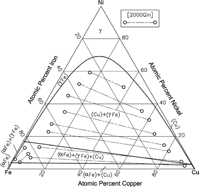
pressure to be constant at one atmosphere. Phase diagrams for materials with more than two components are complex and difficult to represent. An example of a phase diagram for a ternary alloy is shown for a fixed T and P below. Phase diagrams for binary systems ternary phase diagram of Ni-Cr-Fe
Phase Diagrams • Indicate phases as function of T, Co, and P. • For this course:-binary systems: just 2 components.-independent variables: T and Co (P = 1 atm is almost always used). • Phase Diagram for Cu-Ni system Adapted from Fig. 9.3(a), Callister 7e. (Fig. 9.3(a) is adapted from Phase Diagrams of Binary Nickel Alloys , P. Nash










0 Response to "39 cu ni phase diagram"
Post a Comment