41 what is the difference between a context diagram and diagram 0
The system context diagram (also known as a level 0 DFD) is the highest level in a data flow diagram and contains only one process, representing the entire system, which establishes the context and boundaries of the system to be modeled. It identifies the flows of information between the system and... A Context Diagram (sometimes also referred to as a Level-0 Data Flow Diagram) is a common tool that Business Analysts use to understand the context of an entity being examined. There should only be one process per Context diagram and it is generally displayed in the center of the diagram.
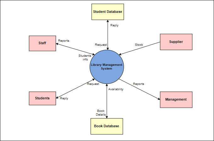
The context diagram provides the abstract view of the information system. It is used for depicting the scope and boundary of the information system. In context diagram external data source, entities, processes are identified during system requirement.
What is the difference between a context diagram and diagram 0
Data flow diagrams were popularized in the late 1970s, arising from the book Structured Design, by computing pioneers Ed Yourdon and Larry They are the sources and destinations of information entering or leaving the system. They might be an outside organization or person, a computer system... A context diagram is a visual representation of the relationship between data and business processes. This diagram has 3 main components which include Read along as we show the symbols when developing a system with a context diagram and their functions. External Entity- an element in the... A context diagram shows the top level view of an Information System (IS) that depicts its boundaries and scopes. A Data Flow Diagram (DFD) specifies the way system would store, process and transform data into information. The increasing levels in these diagrams increase the details of the IS. Chapter 5, Problem 5Q is solved.
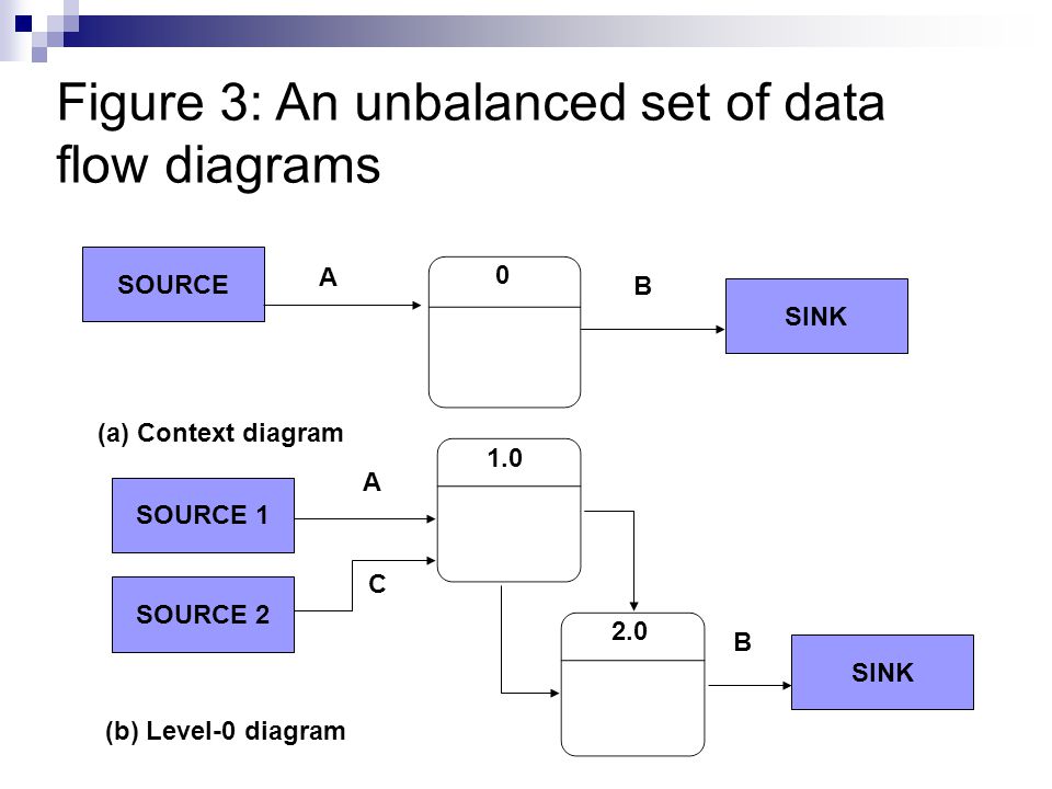
What is the difference between a context diagram and diagram 0. System context diagram. Child process. Which symbol is not used in a context diagram? 4. How would you explode DFDs? 5. Describe a data dictionary and list the types of information it contains. Class Diagram A class diagram is at the heart of UML. It represents the core purposes of UML because it separates the design elements from the Since classes are the building block of objects‚ class diagrams are the building blocks of UML. The diagramming components in a class diagram... Which symbol is not used in a context diagram? A: Emerging role of object oriented analysis and design methods Relationship between various objects ... A context diagram describes a single big process whereas diagram 0 describes the small processes that are linked to a big single process. E.g. if HR is a big process then its sub processes will be number of staff in each department, hiring process for each department, payroll for each staff member, benefits for staff member, etc., that can also be further exploded into processes. Data store symbols are not used in context diagrams.
Nov 06, 2012 · The context diagram established context at the system to be developed that is it represents the interaction at the system with various external entities. Where data flow diagram is a simple graphical notation that can be used to represent a system in the term of input data to the system,various processing carried out on this data and the output ... A Context Diagram is the highest level diagram used in Data Flow Methodologies, and describes the system boundaries and the interaction with the environment. A class diagram shows types and subtype. An entity-relationship diagram shows connections between different sorts of things. Context diagrams are often called "Level 0" data flow diagrams because if one were to put arrows on the connections between sources and targets, the It is not a predefined diagram of SysML or UML, but a variant of block diagrams. 9 In the center of the diagram is the system under development. 2 What Is The Difference Between A Context Diagram And Diagram 0 Which Symbol Is Not Used In A Context Diagram. Data flow diagram (DFD) is the part of the SSADM method (Structured Systems Analysis and Design Methodology), intended for analysis and information systems projection.
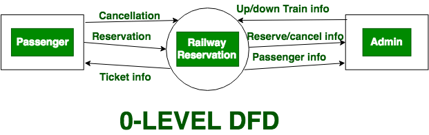
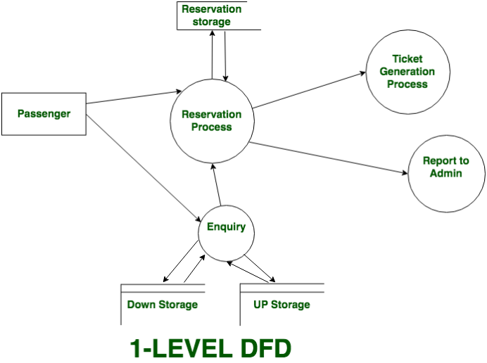
What is an Data Flow Diagram (DFD)? Visually, the biggest difference between the two ways of drawing data flow diagrams is how processes look. In the Yourdon and Coad way, processes are depicted as circles, while in the Gane and Sarson diagram the processes are squares with rounded... UML diagrams help to represent Object Oriented concepts. These diagrams help conceptual modelling and make it simple and easier to understand the system. 1. Overview and Key Difference 2. What is Use Case Diagram 3. What is Activity Diagram 4. Side by Side Comparison - Use Case... Context Diagrams and Data-Flow Diagrams were created for systems analysis and design. But like many analysis tools they have been leveraged for other purposes. For example, they can also be leveraged to capture and communicate the interactions and flow of data between business processes. Context data flow diagram (also called Level 0 diagram) uses only one process to represent the functions of the entire system. It does not go into details as As you saw above context DFD contains only one process and does not illustrate any data store. This is the main difference with level 1 DFD.
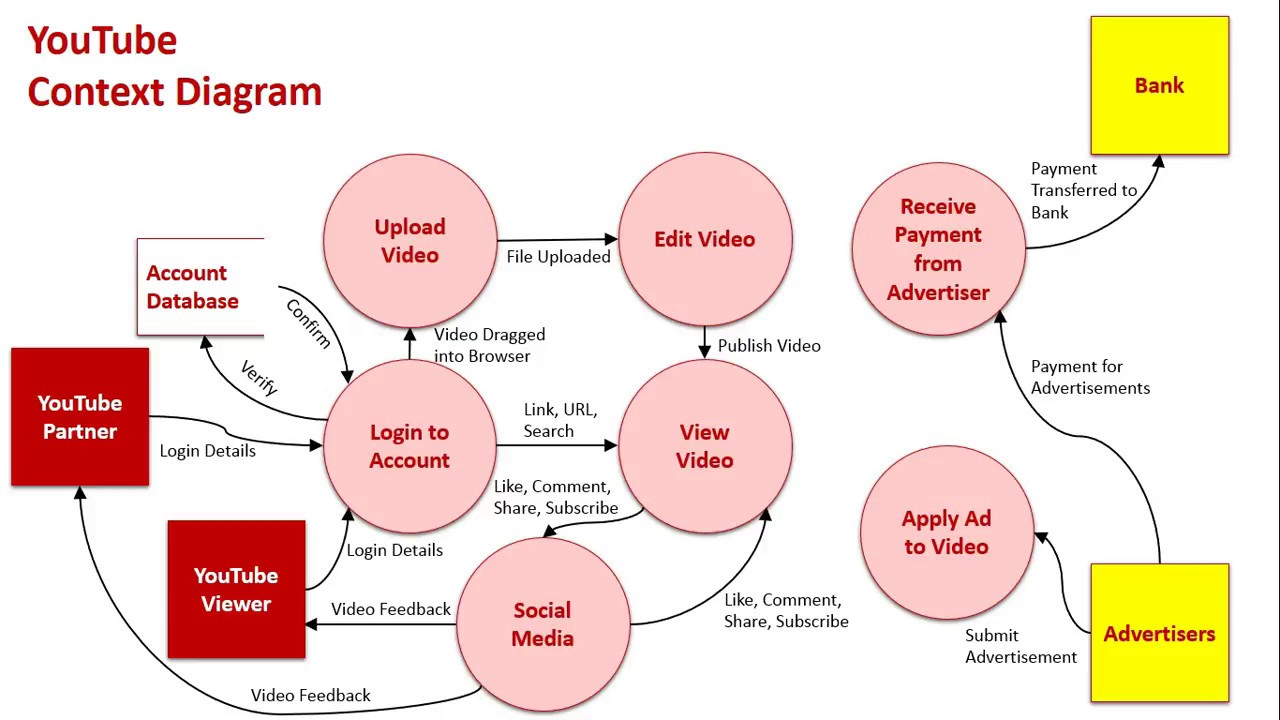
Context & Data Flow Diagrams Sample 1: YouTube
What is a context diagram. A model that shows how your product interacts with outside people, organizations, and/or systems. A data flow is represented by an arrow and a label that represents the type of data that flows between the entities on the context diagram (your product and the external...

The Context Diagram and Data Flow Diagram | Tasstudent.com
they are not different they are similar as level 0 DFD represents the primary individual process in system at highest level it is also called context diagram. It describes the overall system at highest level describing which element is inside and which element is outside the system.....
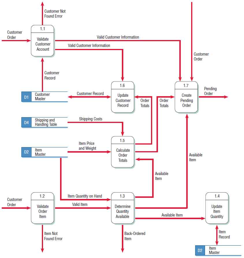
A Data Flow Diagram (DFD) Example
A context diagram is one of the first diagrams you will start creating when you begin looking at software design and development. Step 5: Discuss this diagram with the client (or other important stakeholders) and ensure that your understanding of the problem is the same as theirs.

Software Engineering Data Flow Diagrams - javatpoint
The Difference Between Context and Data Flow Diagrams.
Context diagrams
A system context diagram (SCD) in engineering is a diagram that defines the boundary between the system, or part of a system, and its environment, showing the entities that interact with it. This diagram is a high level view of a system. It is similar to a block diagram.
What is A Context Diagram with Examples | EdrawMax Online
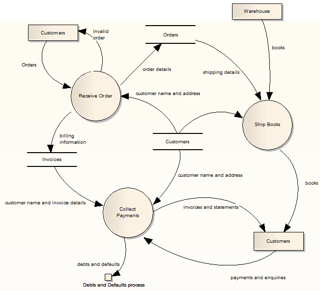
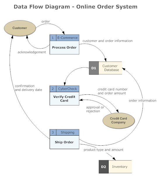
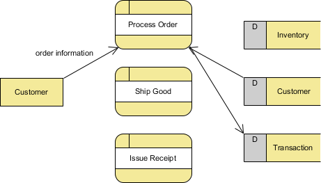
May 08, 2021 · Diagram 0 is a DFD that that shows the first level of detail below the initial context diagram and shows major processes, data flows and data stores while repeating the external entities and data flows that show up in the context diagram. Data stores are not used in a context diagram.

Data Flow Diagram Symbols, Types, and Tips | Lucidchart
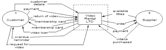
A context diagram leaves out a lot of detail. It focuses on the exchange of data between the system and external entities. The system could be a product, website The context diagram will ensure that you've identified all the external relationships involved. What are the benefits of a context diagram?
What is A System Context Diagram with Explanation Examples
The context diagram is used to establish the context and boundaries of the system to be modelled: which things are inside and outside of the system being modelled, and what is the relationship of the system with these It identifies the flows of information between the system and external entities.

Context Diagram - an overview | ScienceDirect Topics
In Software engineering DFD(data flow diagram) can be drawn to represent the system of different levels of abstraction. 0-level DFD: It is also known as a context diagram. It's designed to be an abstraction view, showing the system as a single process with its relationship to external entities.
Construct a Diagram 0 DFD based on the below scenario | Chegg.com
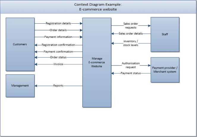
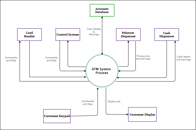
Limitations of Context Diagrams Context Diagram vs. Data Flow Diagram Context Diagram Examples How to Create a Context Diagram with EdrawMax? Differences. Context Diagram. In the diagram above, a context diagram is used to display the Automatic Teller System software plus...

Putting Systems Analysis “Into Context†using the Context Diagram
Unlike the context diagram, the use case diagram does provide some visibility into the system. Each oval inside the system boundary box represents a The use case diagram shows the interactions of the system with its users and some connections between internal system operations, albeit at a high...

System context diagram - Wikipedia
What is the difference between a context diagram and diagram 0? Which symbol is not used in a context diagram? You would need to create a lower diagrams using balancing and leveling techniques to ensure readability. Describe a data dictionary and list the types of information it contains.

Data Flow Diagram: Examples (Context & Level 1), Explanation ...
A context diagram shows the top level view of an Information System (IS) that depicts its boundaries and scopes. A Data Flow Diagram (DFD) specifies the way system would store, process and transform data into information. The increasing levels in these diagrams increase the details of the IS. Chapter 5, Problem 5Q is solved.

Example of a Data Flow Diagram (Level 0) - YouTube
A context diagram is a visual representation of the relationship between data and business processes. This diagram has 3 main components which include Read along as we show the symbols when developing a system with a context diagram and their functions. External Entity- an element in the...

Example of Syntax Error for Rule 9. | Download Scientific Diagram
Data flow diagrams were popularized in the late 1970s, arising from the book Structured Design, by computing pioneers Ed Yourdon and Larry They are the sources and destinations of information entering or leaving the system. They might be an outside organization or person, a computer system...

Data Flow Diagram - an overview | ScienceDirect Topics

What is a Data Flow Diagram | Lucidchart
What is DFD? Explain level 0 and level1 DFD with suitable ...
The Context Diagram and Data Flow Diagram | Tasstudent.com

What is a Data Flow Diagram | Lucidchart

Context diagram (DFD Level 0) for EFDMS and EFD application ...
DATA FLOW DIAGRAM (PART 2) - ppt video online download
Levels in Data Flow Diagrams (DFD) - GeeksforGeeks
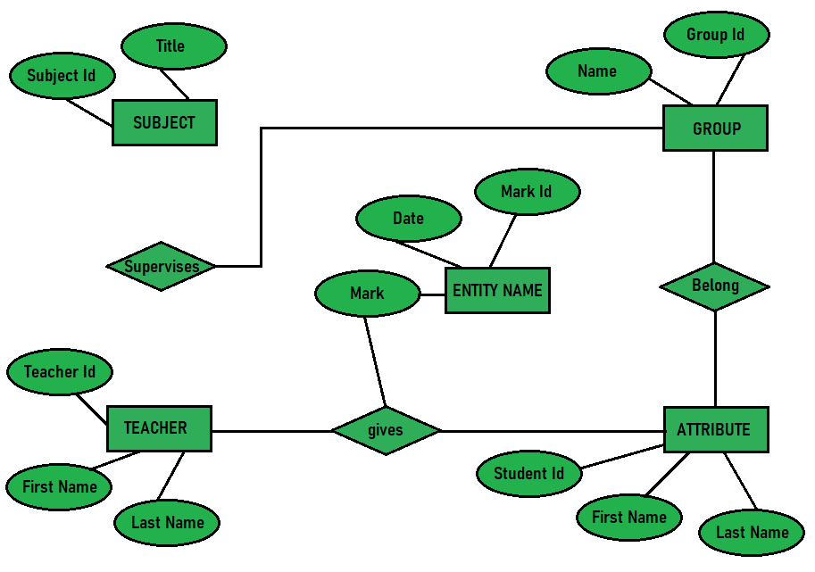
Difference between DFD and ERD - GeeksforGeeks

Context Diagram | Let's think critically about...
Online Clinic Reservation System - Context Diagram | Creately

Data Flow Diagram: Examples (Context & Level 1), Explanation ...
Levels in Data Flow Diagrams (DFD) - GeeksforGeeks

Introduction to Context Diagrams > Business Analyst Community ...

Data Flow Diagram - an overview | ScienceDirect Topics
Data Flow Diagrams | Enterprise Architect User Guide
CPSC 333: Leveled Sets of Data Flow Diagrams

Context Diagram (Level 0). | Download Scientific Diagram

Introduction to Context Diagrams > Business Analyst Community ...

Data Flow Diagram | Gane Sarson Diagram | Cisco Icons | 2 ...
Data Flow Diagram - Everything You Need to Know About DFD
What is Data Flow Diagram (DFD)? How to Draw DFD?

Webby - The PHP Team: Context Diagram
Banking System Data Flow -Context Diagram | Creately
What is A System Context Diagram with Explanation Examples

Context Diagram - an overview | ScienceDirect Topics
0 Response to "41 what is the difference between a context diagram and diagram 0"
Post a Comment