39 mefi 4 wiring diagram
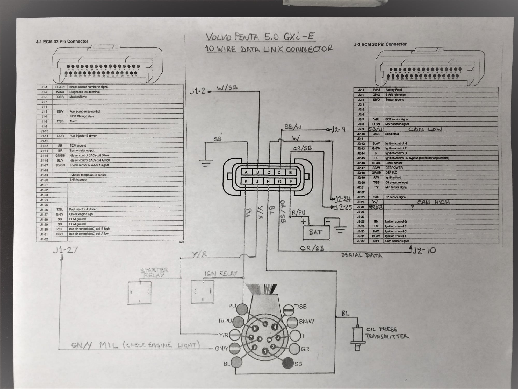
40 mefi 4 wiring diagram - Diagram Online Source PDF section1_m4a | MEFI On-Board Diagnostic (OBD) System Check You should be familiar with wiring diagrams, the meaning of voltage, ohms, amps and the basic It is part of the MEFI engine wiring harness, and is a 10-pin connector, which is electrically connected to Wiring harnesses should be replaced with proper part number harnesses. PDF Marine Electronic Fuel Injection (MEFI) Section 1 General ... You should be familiar with wiring diagrams, the meaning of voltage, ohms, amps and the basic theories of electricity. ... (DLC) (Figure 1-1). It is part of the MEFI engine wiring harness, and is a 10-pin connector, which is electrically connected to the ECM. It is used in the assembly plant to receive information in checking that the engine is
BillaVista.com-MEFI-4 Fuel Injection Tech Article by ... MEFI-4 Inputs & Outputs The fourth-generation of GM Powertrain's Marine ECM has several important capabilities and features, including: Coil-Near-Plug Capability - Provides the engine builder the opportunity to incorporate a coil-near-plug ignition system for more accurate ignition timing and better spark.
Mefi 4 wiring diagram
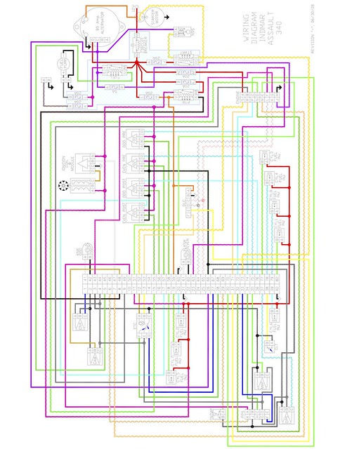
MEFI 4 ECU Wire Harness - Ram Jet 350 - Ed Rinke Performance ECM Wire Harness, Ram Jet 350 Designed for use with the 350 Ram Jet engine. $364.57 $349.99. Add to cart. MODULE ASM,ENG CONT *RAMJET 350*. $775.08 $715.01. Add to cart. Jumper Harness, MEFI 3 to MEFI 4. $461.57 $443.11. Add to cart. Mefi 4b, Mefi4b, Indmar, Malibu | Mefi 4, wiring diagram ... Mefi 4, wiring diagram, Indmar, 350 chev, Malibu, Mefi4b, loom indmar, PDF Table of Contents - motooff.ru ECM Wiring Diagram - MEFI 3 (V6 and Small Block V8) (2 of 4). . . . . . . . . . . . . . . . 1-35 ECM Wiring Diagram - MEFI 3 with Mercury Distributor (V6 and Small Block V8) (3 of 4. )1-36 ECM Wiring Diagram - MEFI 3 with GM EST Distributor
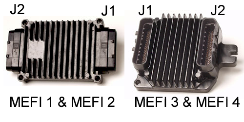
Mefi 4 wiring diagram. OBD Diagnostics - ECM Connectors The MEFI 1-4 family of controllers all use the same ECM connectors for J1 and J2, even though the style of the ECM package is different for the MEFI1 and MEFI2 vs the MEFI3 and MEFI4. The connectors look similar, and are the same except for a keying part which assures that the connectors are not plugged into the wring place on the controller ... Mercruiser 7.4 Wiring Diagram Mercruiser 7.4 Wiring Diagram. Mercruiser L Wiring, Mercruiser L Marine Engine Wiring Diagram Mercruiser L Performance Spec's, Mercruiser engine specifications including. Thunderbolt IV mounted on exhaust elbow wht/red from module to dis. wht/grn from module to dis. gray neg on coil to tac. and to module. purple. PDF MEFI-1thru4 Fox Marine Installation and Operating Instructions Some have red and black wires. Connect the oil pressure data cable's blue or red wire to the S terminal. Connect the brown or black wire to the G terminal. Revised 05/29/21 Page 4 of 7 Plug the engine gateway into the boat's 10-pin diagnostic connector. This connector may already be plugged in to a cap for protection. Mefi 4 & 4b Diagnostic Manual (l510005p) | Electrical ... MEFI 4 - PCM 6.0L. Fuel Metering System 3B - 11. 3. Once installed, pull on both sides of the fitting in order to make sure the connection is secure. 12787. 4. Install the retainer on to the quick-connect fitting. 1238589. MEFI 4 - PCM 3B - 12 Fuel Metering System. 6.0L Fuel Rail Assembly Replacement Remove or Disconnect 1. Relieve the fuel ...
The Complete MEFI ECM Solution - Tuning, Data Logging ... The MEFIburn Scan & Tune TM package comes complete with everything you will need to interface to generations of the MEFI controllers, including MEFI-1, MEFI-2, MEFI-3, MEFI-4, MEFI-4A, MEFI-4B: A USB - MEFI Interface Cable. This has the 10-pin Delphi MEFI connector on one end and plugs into your computer's USB port on the other end. PDF 4.3l 5.7l Mefi 4 Engine Wiring Diagram - Marine Power USA 4 1 3 2 Bosch Manifold Absolute Pressure (MAP)/Intake Air Temperature (IAT) Sensor Engine Coolant Temperature ... MEFI System Relay 19 J2 6 J1 PPL 902 PNK 439 BLK 150 BLK 150 Fuse Block GRY 120 Fuel Pump BLK 150 PPL 903 ... twisted wire. CAN Hi 21 J2 IAT Sensor B Injector Driver A Pressure Sense Driver B (VSS) VF Tried out new MEFI 4 b software today - Chevy Message ... Re: Tried out new MEFI 4 b software today 10-06-06 11:10 AM - Post# 1011055 In response to monty56 I found out the scoop on the MEFI 4b wideband O2. You just hook up the O2 sensor wires 0-5 V to connector J2 pin 6 and the ground wire to J2 pin 3, of if your MEFI harness has an O2 sensor plug, the 5V wire goes to pin B and the ground to pin A in the oxygen sensor connector. CBM Motorsports | LS Engine Support, FAQ, Software and ... 2.4 DI Ecotec Wiring Harness Diagram - Open and Download to Device. 2.4 Ecotec MEFI 5 Wiring Harness Diagram - Open and Download to Device. 2.5 LCV DI Wiring Harness Diagram - Open and Download to Device. Ecotec Sensor Location #1 - Open and Download to Device. Ecotec Sensor Location #2 - Open and Download to Device.
PDF Ram Jet 350 MEFI 3 to MEFI 4 Conversion Kit RAMJET 350 Electronic Fuel Injection (EFI) MEFI 3 to MEFI 4 Conversion Kit 12499116 Getting Started Installation of this upgrade kit is straight forward; however, installation of the exhaust bung requires welding. ... If you have customized your wiring harness for your specific application it may be easier to only remove the Mefi 4 Wiring Diagram Section 1 - General The wiring schematics and circuit identifications are for the MEFI. 4/4B originally.Complete Engine Wiring Harness including: All engine sensor connectors. ALDL Connector. Fuel Pump Relay. Switched Power Ignition Relay. Mefi 4b, Mefi4b, Indmar, Malibu Cruise Control Wiring. TCC/Switch Wiring. Tach Wiring. MEFI™ ECM Ver. 4. PDF Boat Engine Electrical Wiring Schema Wiring Schematics Distributor Kit Wiring Diagram J1939 to NEMA2000 Wiring MEFI 4 MEFI 4 Engine Controls Schematic 4.3L - 5.7L MEFI 4 ECM Circuit Board Layout (5.7-6.0-8.1L) MEFI 4 Engine Controls Schematic 6.0L MEFI 4 ECM Engine Wiring Diagram 8.1L 5.7L Wiring Harness Schematic (472605) ujhgfdfddd.blogspot.com It doesn't indicate that acquiring publication Indmar Mefi 4 Wiring Diagram will certainly indicate that you could acquire this globe. Merely for joke! Merely for joke! Reviewing an e-book Indmar Mefi 4 Wiring Diagram will certainly opened an individual to think much better, to maintain smile, to amuse themselves, and to encourage the expertise.
PDF MEFI 4 / 4B DIAGNOSTIC MANUAL - Pirate 4x4 MEFI 4 - PCM Marine Electronic Fuel Injection (MEFI) Section 1 General Information Contents ... You should be familiar with wiring diagrams, the meaning of voltage, ohms, amps and the basic theories of electricity. You should also understand what happens if a circuit becomes open, shorted to ground
Mefi 3 Wiring Diagram - schematron.org This article covers the fourth-generation of the GM MEFI system, known as It has two connectors and three mounting bosses. . Here is the wiring diagram. Section 8 - ECM Wiring. 8 - 3. Marine. MEFI 1 ECM Connector Identification (2 of 2). J ECM 32 WAY OUTPUT CONNECTOR. ECM PIN. CKT (WIRE).
PDF Table of Contents - motooff.ru 1-4 - EFI SYSTEM COMPONENTS/OPERATION MerCruiser EFI II (1003) MEFI 3 ECM Input and Sensor Descriptions. ECM. a b c d e h j f g i k o q s t u v p r l m n. 1. -Audio ...
Mefi 4 ECM MEFI™ 4 / 4a / 4b ELECTRONIC CONTROL MODULES Mefi™ 4, 4a, 4b ECM `s The ecm will ship blank and without a calibration. If available in our tune inventory, we are happy to place a baseline tune in the computer at no additional cost. Please call or email us for engine applications and program details. For specs, options and pricing.
Mefi 3 Wiring Diagram All 3-wire The wiring schematics and circuit identifications are for the MEFI. 4/4B originally. Section 8 - ECM Wiring. 8 - 3. Marine. MEFI 1 ECM Connector Identification (2 of 2). J ECM 32 WAY OUTPUT CONNECTOR. ECM PIN. CKT (WIRE). ECM Wiring Diagram - MEFI 3 with Mercury. Distributor (V6 and Small Block V8) (3 of 4).
Racepak Gauge Help - race-deZert A- Is the trans temp gauge sensor wire, I assume I need the sensor to go into the trans and I will be good to go on this one B1- connects to mefi module and goes through part of the existing harness B2- Open end with four wires- Red, Green, Black, and White C- Mefi 4 module that may be worthless D-back to gauges in dash.
PDF Mefi 4 j1-1 468 lt blu/blu knock sensor 2 signal j1-2 451 blk/wht diagnostic "test" terminal master / slavej1-3 j1-4 blu/wht general warning 2 (oil pressure) (input) j1-5 emergency stop j1-7 rpm change state j1-8 buzzer j1-9 check gauges lamp (engine over temp) j1-10 ecotec crank 2.2 j1-11 468 dk grn fuel injector b driver …
4 Wire Wiring Diagram - easywiring The following diagram is a representation of the general inputs and outputs of the mefi 4 system. A wiring diagram is a simplified traditional pictorial representation of an electric circuit. This diagram is a thumbnail. Here s a basic look at how the sensors in the speed density mefi 4 fuel injection work.
Wiring Schematics - Marine Power USA Wiring Schematics - Marine Power USA Wiring Schematics Distributor Kit Wiring Diagram J1939 to NEMA2000 Wiring MEFI 4 MEFI 4 Engine Controls Schematic 4.3L - 5.7L MEFI 4 ECM Circuit Board Layout (5.7-6.0-8.1L) MEFI 4 Engine Controls Schematic 6.0L MEFI 4 ECM Engine Wiring Diagram 8.1L 5.7L Wiring Harness Schematic (472605) MEFI 5
CBM Motorsports MEFI 4 Electronic Control Modual Technical ... MEFI™ ECM This is the MEFI™ ECM version 4. It has two connectors and three mounting bosses. Back side of the ECM. Note the part number on the sticker. In this case "12575479". All MEFI™ ECM's have a part number like this that can be used to determine the "series" or "generation" that the MEFI™ system is. MEFI™ ECM version 1, 2.
Mefi 4 Wiring Diagram - schematron.org The following diagram is a representation of the general inputs and outputs of the MEFI-4 system. Here's a basic look at how the sensors in the speed-density MEFI-4 fuel injection work. Engine load is primarily determined by sensing the current engine speed and reading the manifold pressure via the manifold absolute pressure (MAP) sensor (this.
PDF Table of Contents - motooff.ru ECM Wiring Diagram - MEFI 3 (V6 and Small Block V8) (2 of 4). . . . . . . . . . . . . . . . 1-35 ECM Wiring Diagram - MEFI 3 with Mercury Distributor (V6 and Small Block V8) (3 of 4. )1-36 ECM Wiring Diagram - MEFI 3 with GM EST Distributor
Mefi 4b, Mefi4b, Indmar, Malibu | Mefi 4, wiring diagram ... Mefi 4, wiring diagram, Indmar, 350 chev, Malibu, Mefi4b, loom indmar,
MEFI 4 ECU Wire Harness - Ram Jet 350 - Ed Rinke Performance ECM Wire Harness, Ram Jet 350 Designed for use with the 350 Ram Jet engine. $364.57 $349.99. Add to cart. MODULE ASM,ENG CONT *RAMJET 350*. $775.08 $715.01. Add to cart. Jumper Harness, MEFI 3 to MEFI 4. $461.57 $443.11. Add to cart.













0 Response to "39 mefi 4 wiring diagram"
Post a Comment